Max “Litruv” Boonzaayer came up with a modular design where design pieces can be quickly combined to create MIDI controllers with any number of knobs & sliders.
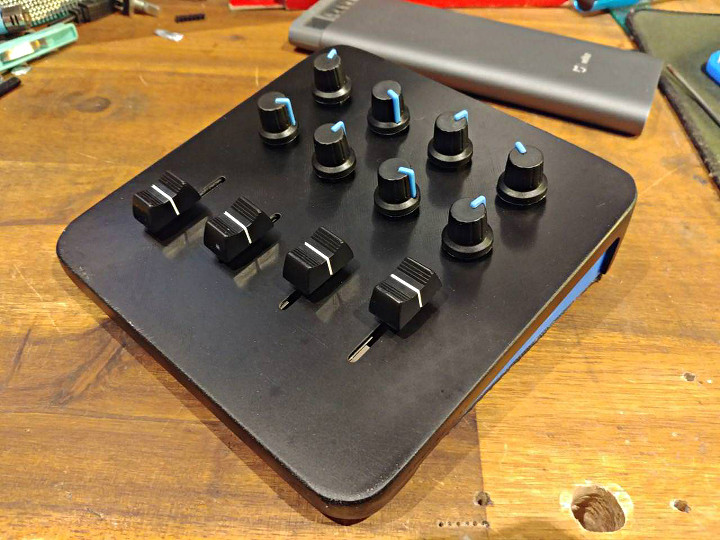
The idea behind the project was to design modules to connect to a 10x10cm PCB.
|
||
|
Shopping Cart
|
| Home | Products | Teensy | Blog | Forum |
Max “Litruv” Boonzaayer came up with a modular design where design pieces can be quickly combined to create MIDI controllers with any number of knobs & sliders.
The idea behind the project was to design modules to connect to a 10x10cm PCB.
Not your run-of-the-mill webcam, Mike’s photobooth uses a Canon DSLR camera and softbox lighting for superior quality photos. The booth does preview, customization, printing, and can automatically upload to the internet, but is easy for anyone to use with a giant arcade button.
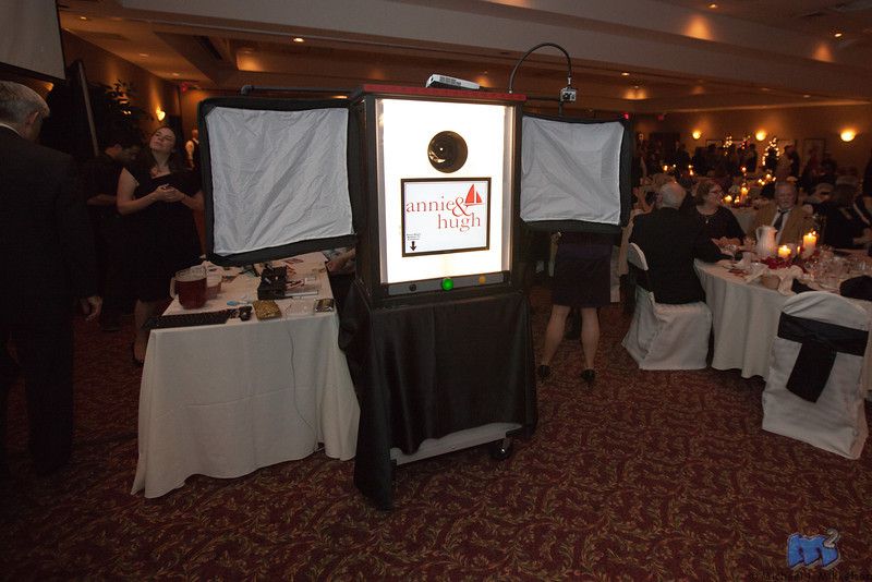
As the official photographer for a good friend’s wedding, Mike decided he wanted an “open air booth” with built-in softbox lighting and could use a dSRL camera. It also needed to be easy to use as the official photog he didn’t want it to consume his time at the wedding.
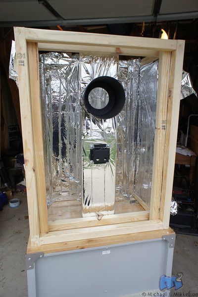
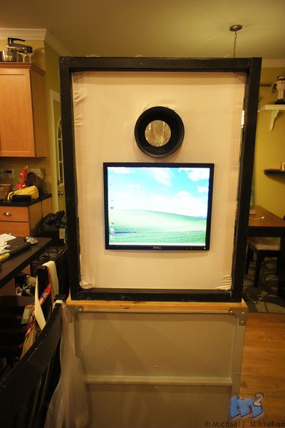
The photo booth is built on a rolling tool cabinet making it easy to cart around. It runs the dSLR Remote Pro software on an old HP Pentium 4 2.8 Ghz computer. A Teensy is used to add arcade style buttons to simulate keyboard shortcuts in the software to allow the user to switch between photo/video modes, start the image/video capture, and enable/disable the camera’s live view.
Code for the project can be found on this blog page.
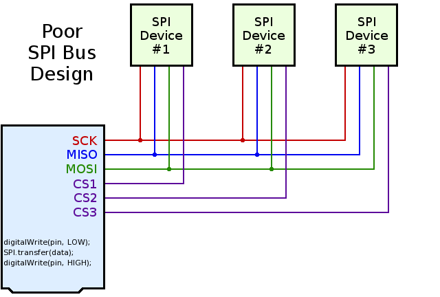
Most Arduino SPI tutorials show this simple but poor SPI bus design:
Better SPI bus design can prevent conflicts. 3 simple improvements are needed:
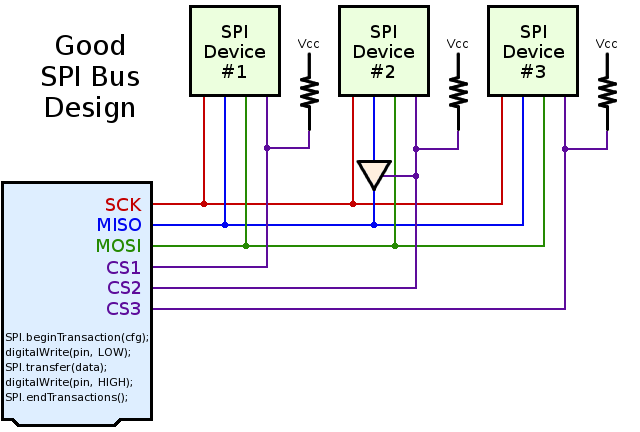
When multiple SPI devices are used, and especially when each is supported by its own library, pullup resistors are needed on the chip select pins.
Without a pullup resistor, the second device can “hear” and respond to the communication taking place on the first device, if that second device’s chip select pin is not pulled up. This is easy to understand in hindsight, but it can be temendously confusing and frustrating to novice Arduino users who purchase shields or breakout boards without pullup resistors. Each SPI device works when used alone, but they sometimes mysteriously fail when used together, only because both devices are hearing communication meant to initialize only the first device!
A simpe workaround for devices without pullup resistor involves adding code at the beginning of setup.
    void setup() {
      pinMode(4, OUTPUT);
      digitalWrite(4, HIGH);
      pinMode(10, OUTPUT);
      digitalWrite(10, HIGH);
      delay(1);
      // now it's safe to use SD.begin(4) and Ethernet.begin()
    }
Most SPI chips will tri-state (effectively disconnect) their MISO pin when their chip select signal is high (inactive).
However, some chips do not have proper MISO tri-state behavior. Fortunately, checking MISO tri-state is easy, especially when prototyping on a breadboard. Just connect two 10K resistors to the MISO line, like this:
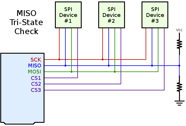
When all SPI chips are disabled, the MISO signal should “float” to approximately half the Vcc voltage. If any device is still driving the MISO line, you’ll see a logic high (usually close to 3.3V or 5.0V) or logic low (close to zero volts). This test is so easy, it should always be performed by designers of Arduino compatible products.
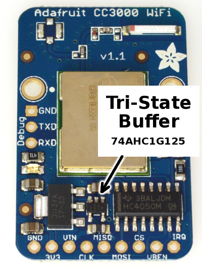
Arduino shields and breakout boards with poorly-behaved chips should always include a tri-state buffer. Adafruit’s CC3000 breakout board is a good example:
Newer versions of Arduino’s SPI library support transactions. Transactions give you 2 benefits:
These improvements solve software conflicts, allowing multiple SPI devices to properly share the SPI bus.
A typical use of transactions looks like this:
    SPI.beginTransaction(SPISettings(14000000, MSBFIRST, SPI_MODE0));
    digitalWrite(chipSelectPin, LOW);
    SPI.transfer(mybyte1);
    SPI.transfer(mybyte2);
    digitalWrite(chipSelectPin, HIGH);
    SPI.endTransaction();
SPI.beginTransaction() takes a special SPISettings variable, which give the maximum clock speed, the data order, and clock polarity mode. The speed is give as an ordinary number, expressing the maximum clock speed that device can use. The SPI library will automatically select the fastest clock available which is equal or less than your number. This allows your code to always use the best speed, even on board with different clock speeds.
If your code will ever call SPI library functions from within an interrupt (eg, from attachInterrupt), you must call SPI.usingInterrupt(). For example:
    SPI.begin();
    SPI.usingInterrupt(digitalPinToInterrupt(mypin));
    attachInterrupt(digitalPinToInterrupt(mypin), myFunction, LOW);
If you are developing a library that must be compatible with older versions of Arduino, which lack these SPI transaction functions, you can use SPI_HAS_TRANSACTION to check for the new version. For example:
    #ifdef SPI_HAS_TRANSACTION
    SPI.beginTransaction(SPISettings(2000000, LSBFIRST, SPI_MODE1));
    #endif
Many SPI-based products for Arduino do not work well together. My hope is this information can help all makers of Arduino compatible devices to achieve much better compatibility.
Long-term, sharing of knowledge is needed. Please share this information and ask makers of SPI devices and libraries to consider these suggestions.
This article may be shared and copied under the terms of the Creative Commons Attribution 4.0 International License. Please, copy & share! 🙂
![]()
This article was originally published on the DorkbotPDX website, on November 24, 2014. In late 2018, DorkbotPDX removed its blog section. An archive of the original article is still available on the Internet Archive. I am republishing this article here, in the hope it may continue to be found and used by everyone using SPI chips, and especially companies making SPI-based products for the Arduino community.
Adam Haile at Manical Labs found a way to make his beloved trackball mouse cool by making a billiard ball arcade trackball mouse.
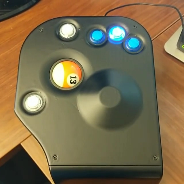
Not only is Adam a bit obsessed with the trackball mouse, but he’s also a billiards fan. So when he saw a character using a 9-Ball mouse in the movie Oceans 8, he knew he had to have one.
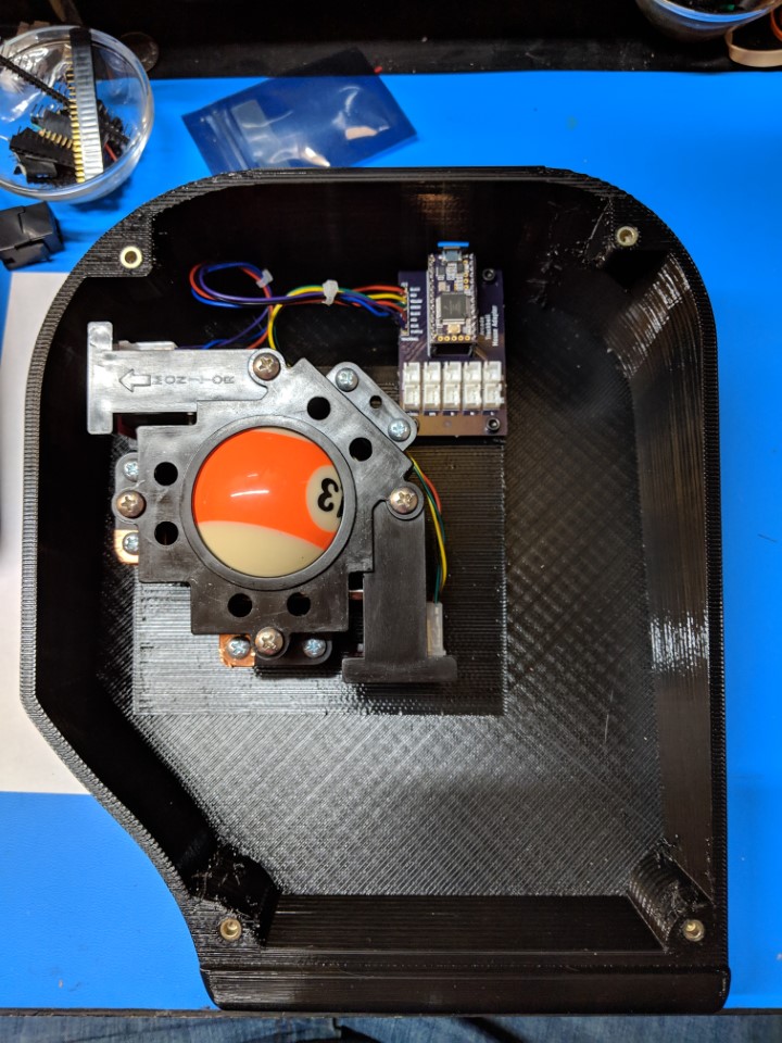
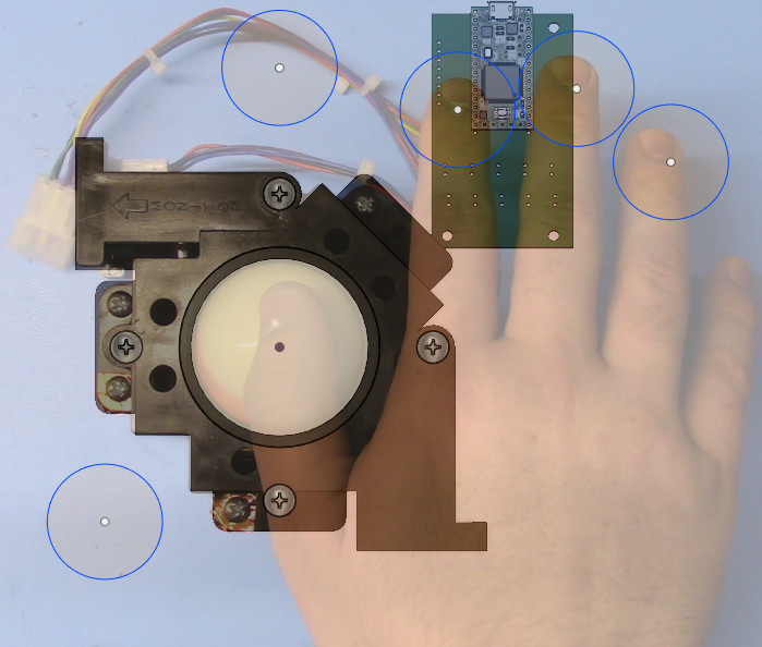
He used an arcade trackball as a base and added some LED arcade buttons. A 3-D printing housing was create to custom fit his hand. A custom PCB made it easy to wire the buttons and trackball to the Teensy and also made it easy to mount the electronics.
The USB HID functionality of a Teensy along with the Encoder library made quick work of the code for the project.
Code for the project as well as the PCB designs and CAD files are available on GitHub.
Ben McInnes, Adoné Kitching, Jason Sutherland, and Luc Wolthers created an amazing game – Guitar Wizards.
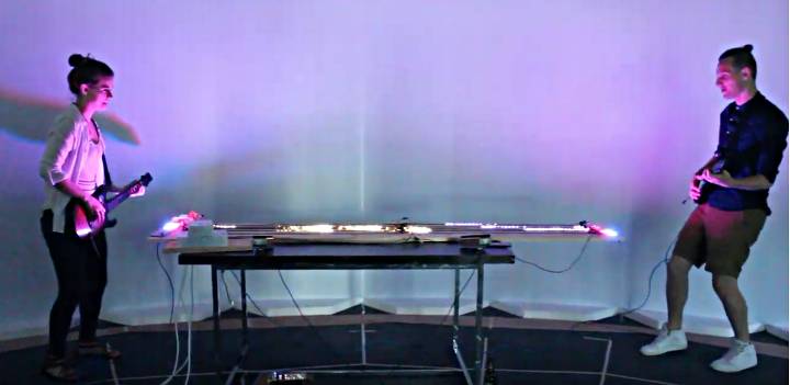
Guitar Wizard is a game based of the classic Guitar Hero game. Rather than play for points, the players battle each other, head on, playing riffs on the modified Guitar Hero controllers, shooting LED notes at each other. The opposing player blocks the notes by playing their own notes and chords.
This amazing, interactive game is powered by a Teensy 3.6, has over 2,000 WS2812B LEDs, and uses the FastLED library.
You can read more about the inspiration for the game here.
Wojciech Sura (forum user spook) has made a very useful tool for creating and editing fonts for the ILI9341 display
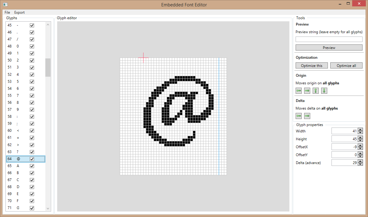
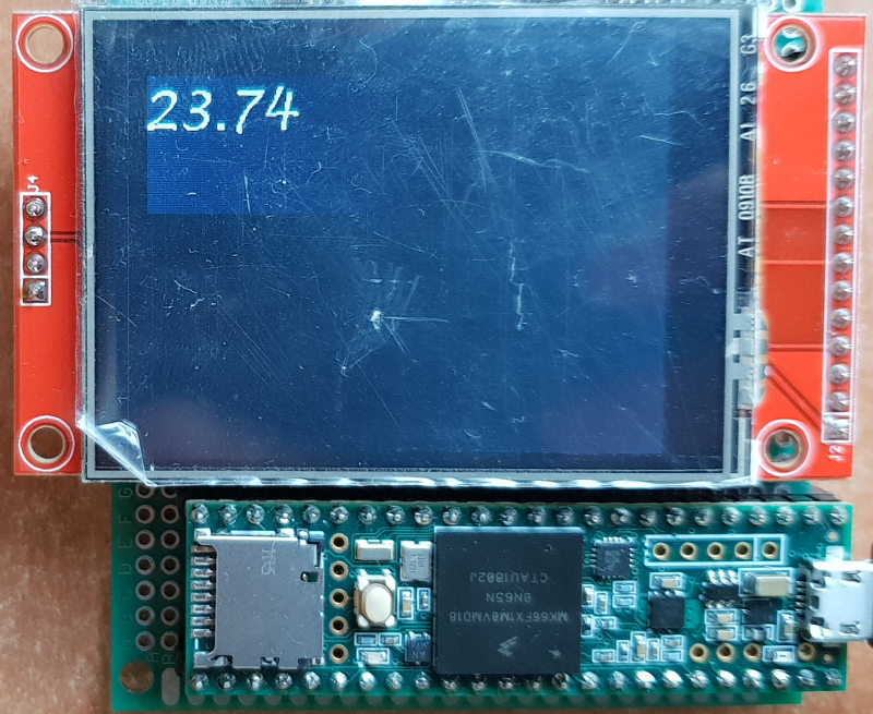
Until now, the only way to get custom fonts in the ILI9341 display has been a converter script. Now you can actually create & edit fonts with a beautiful graphics editor.
This useful app includes a number of features, including:
The editor is available in this GitLab repository. It does require Visual Studio 2017 to build. If you don’t have access to Visual Studio, spook has posted a build in this forum thread.
Petros Kokotis developed a replacement for the ever popular SID chip (MOS Technology 6581/8580) using a Teensy 3.6.
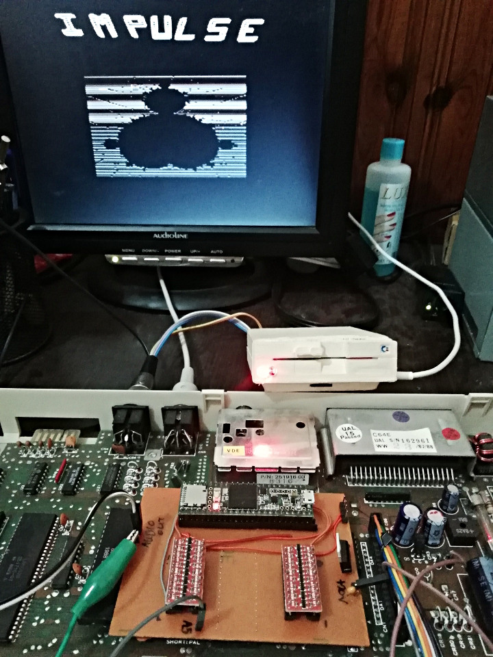
The SID was a popular sound synthesizer chip from the 1980s used in the Commodore 64 computer. Much to the dismay of many nostalgic computer enthusiasts, it hasn’t been manufactured for many years.
Petros used a Teensy 3.6 and some level shifting boards to intercept address and data lines of a SID chip. He also used the Teensy Audio Library and the ReSID Library by Frank Bösing (from his C64 emulation).
Code for the project can be found in this GitHub repository.
gdsports has made a joystick splitter that solves the problem of the Microsoft Xbox Adaptive Controller (XAC) ignoring the hat switch on the Logitech Extreme 3D Pro Flight Stick.
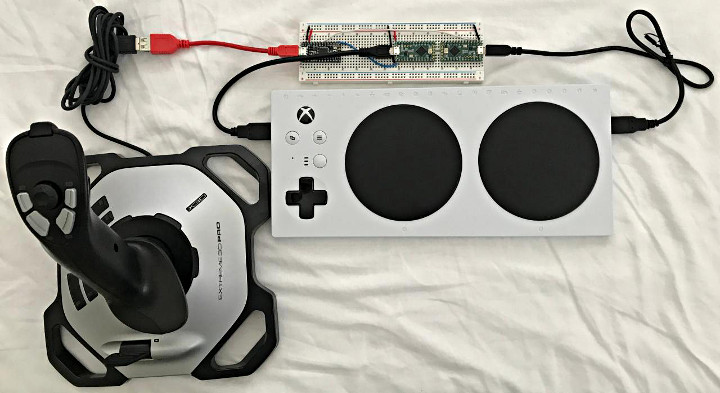
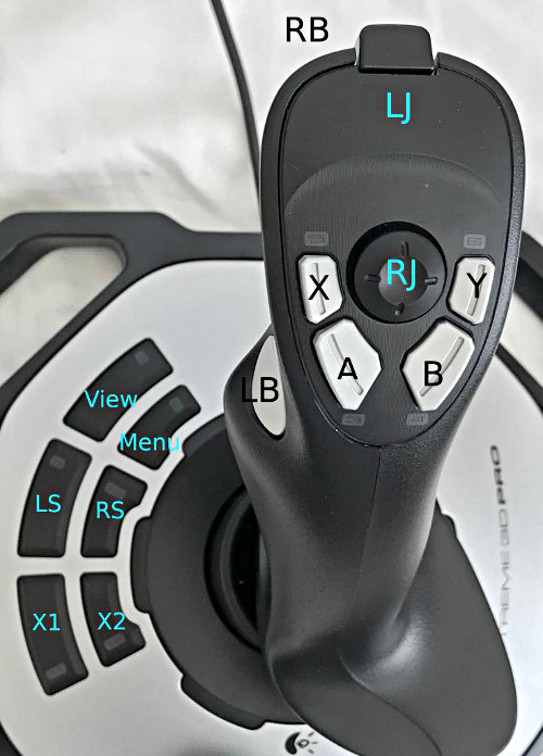
The splitter uses 2 Teensy-LC boards and an Adafruit ItstyBitsy to remap the joystick controls and maps the Logictech Flight Stick to the XAC in the following ways:
Code for the project can be found in this Github repository.
Often the question is asked, what is the simplest way to get modular synth control voltage (CV) into an analog input pin?
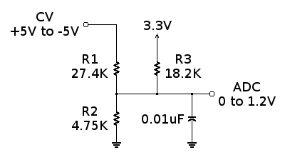
This simple circuit using only 3 resistors and 1 capacitor converts the -5V to +5V CV signal range to the 0 to 1.2V ADC input range.
For Teensy 3.2, 3.5 and 3.6, you would use analogReference(INTERNAL) to configure for the 0 to 1.2V range. Then you can read the CV signal at any time with analogRead().
While this circuit is the simplest and easiest way, it is not necessarily the best way. The input impedance, or load placed on the CV signal, it 31K ohms, rather than the standard 100K impedance normally used for modular synthesis systems. This forum discussion goes into the circuit’s limitations and suggests more advanced ways using opamps.
Originally this article was published on the DorkbotPDX website. Since that time, the DorkbotPDX blog section has vanished. I’m reposting it here, to preserve this info. A copy of the original can also be found at the internet archive.
Brian Taylor of Bolder Flight has put together a great tutorial on Pulse Width Modulation (PWM).
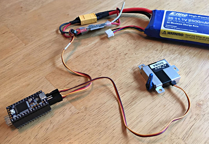
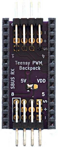
PWM is commonly used to control servos and electronic speed controllers (ESC) and is useful for many projects. This tutorial explains PWM and introduces how to wire up and command a servo Part 2 of the tutorial go over reading PWM commands.
The tutorial features the PWM Backback by Bolder Flight. This handy backbpack makes it easy to hookup RC Servo Motors to your Teensy. It features 8 channels of 16 bit PWM output; bused ground, power, and standard servo connectors; and option SBUS communication input.