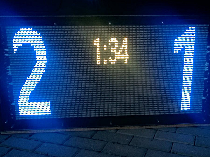
Wolfgang Höhne submitted his video wall project that he recently made. The field where his football club plays it can be difficult to know the score and time remaining. Wolfgang created a video wall to display this information. It’s remotely updated by the announcer to keep spectators informed on the game. Not every field is equipped with large signboards to display match information. This project is a great way to solve that problem.
There’s a good write up of the project, including the code, over on Hackster.io.
Adrian Godwin submitted the Phantom Limb, a robotic prostetic arm created by The Alternative Limb Project and game company Konami.
The design for the arm was inspired by the world of Metal Gear Solid. The arm is a elegant and beautiful design and is a far cry from many of the common prosthetic designs we are used to seeing. Adrian let us know that a Teensy 3.2 is used in the arm to handle lights, comms, and power control.
This video tells the story of how the arm came to be and an interview with James Young, the gentlemen wearing the arm.
Marcel Boonman created a thinking dodecahedron he describes as a metaphor to simulate the dyslexic way of information processing: ‘conceptual thinking’. The environment serves as input to create an ‘imaginary object’. This is a very interesting project and it’s well worth watching the video.
The project uses a Teensy 2.0 and sensors to measure color, illumination, sound, temperature, humidity, and atmospheric pressure. The measurements from these elements are used to produce a color. The Dodecaeder refers to the fifth element the ether, which is also seen as the mind or in this case the imaginary; A mental representation of multiple ideas (including experiences) that are summarized in an imaginary object.
This video gives a great over view of the build process. My favorite part is seeing a wagon, loaded with beach gear, cruise easily up and over a sand dune.
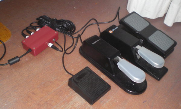
Jon Payne created his own MPC (Music Production Center). He was inspired by an MPC and the DJ Tech Tools MIDI Fighter and decided to create and build a stand alone project that is a combination of the two. This is a really impressive DIY project. It sounds awesome and looks great.
While Jon describes it as a work in progress, it is functional with more features being planned.
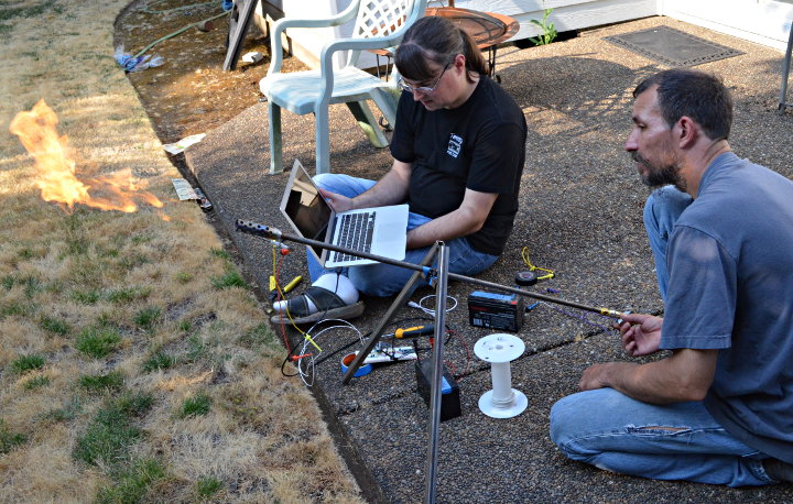
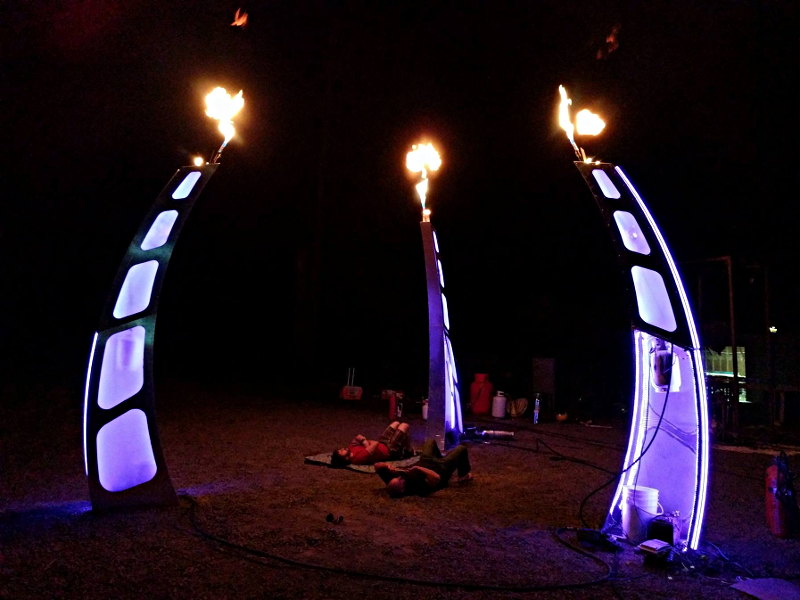
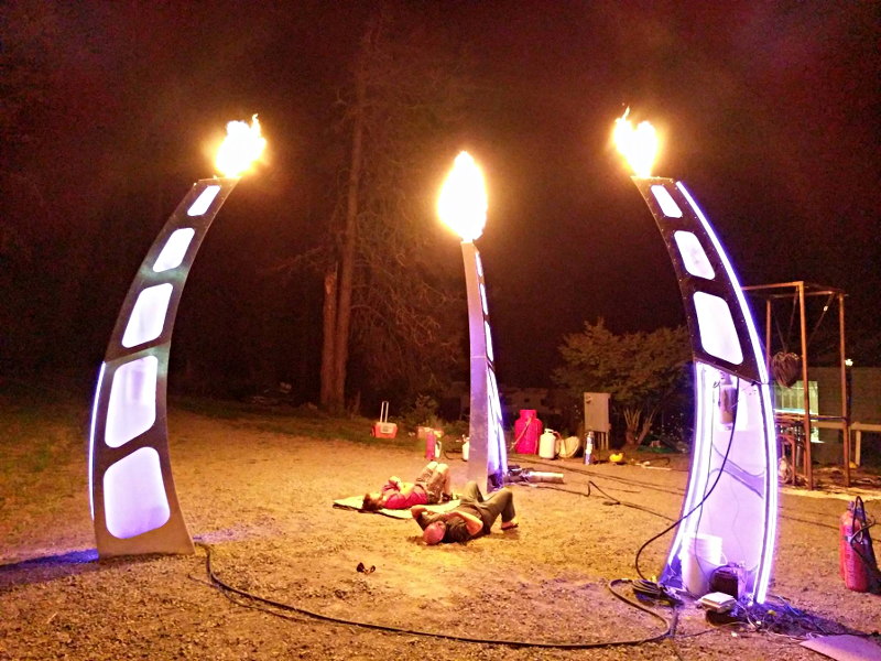
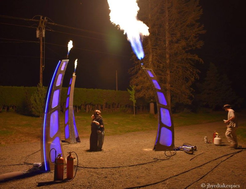
I recently built flame sensing electronics for Martin “Moltensteelman” Montesano’s “Three Wishes” art project to be shown at Burning Man.
As a safety precaution, certain types of fire art installations are required to use sensors on their pilot lights. If wind blows out the pilot, the gas must automatically turn off and other valves controlling high pressure propane directed at that pilot must be prevented from opening.
In this article, I’d like to share with you details of how I built a circuit board for Martin’s project to meet these requirements.
Safety First Disclaimer First
This Information (web page and related hardware and software files) are provided “as is” and without warranty of any kind, expressed or implied, including but not limited to the implied warranties of merchantability and fitness for a particular purpose. In no event shall PJRC.COM, LLC or Paul Stoffregen be liable for any direct, indirect, incidental, special, exemplary, or consequential damages arising in any way out of the use of this Information, even if advised of the possibility of such damage.
My hope is you’ll find this article interesting. If you do make use of it, remember it’s something you found for free on the Internet. Ultimately it’s your responsibility to manage and accept responsibility for the risks of any project you build.
How To Sense A Flame
There are at least 3 ways to sense fire.
Infrared Light: If you search for flame sensors and Arduino, nearly all tutorials and inexpensive products use a simple IR diode or photo-transistor circuit. Infrared light also comes from many other natural and man-made sources, making this approach very difficult to implement reliably. The absolute last thing you want in this application is a false reading allowing high pressure propane to flow!
Heat / Temperature: Thermocouples and Thermopiles are commonly used in water heaters and gas fireplaces. However, temperature sensing can be quite a challenge for an outdoor application exposed to wind and made with metals that can remain hot for quite some time.
Conductivity / Flame Rectification: Modern gas furnaces use this highly reliable technique. Gas flames are conductive and act as a rectifier, similar to a diode. The rectification effect is supposed to be due to a difference in the mobility of the positive ionized particles (burning fuel) and free electrons. Applying a voltage to the flame can move the electrons much moreso than the positively charged ions. The best explanation I’ve found is in this paper by Andreas Möllberg.
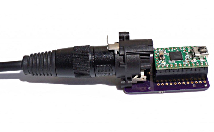
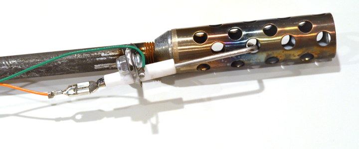
Martin had already purchased this flame sensor rod (Rheem 62-23543-01), based on the fact that it’s the sensor used in a common furnace, that it has a convenient L-shape which works nicely for his art’s pilot light design, and that it’s only $7. So the path of flame rectification sensing was chosen…
He also rigged up 1 of the Three Wishes pilot lights to a regulator and fitting so I could run in in by back yard from my barbeque’s propane tank!
With this sensor and test gear, I started on electronics to make it actually work.
Flame Rectification Circuitry
I must confess, before this project I had never even heard of flame rectification. Reading Möllberg’s paper, it was clear the flame acts like a diode with a very high value resistor in series. Many guides exist for training furnace technicians with good info. So the basic idea is to apply a substantial AC voltage to the flame and then look for a tiny pulsed DC current.
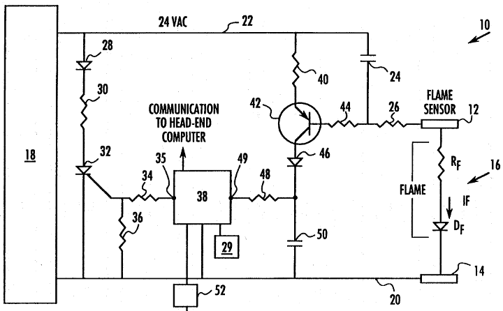
After a couple false starts, a little more searching turned up several patents. I tried a couple of these, ultimately settling on US5439374, partly because it allows an actual analog reading (many circuits are just flame vs no-flame indicators), and partly because it expired in 2013.
US5439374’s basic idea is current can only take 2 paths to get to the flame, either through capacitor #24, or through the resistors and transistor. Since capacitors can only pass AC current, if any net DC current flows through the flame, it must also flow through the transistor’s base-emitter junction.
An amplified copy of the DC current flows through the transistor and diode, causing capacitor #50 to charge up. Higher DC flame conduction causes this capacitor to charge up faster.
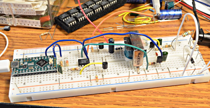
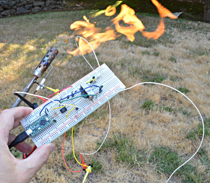
I built an adaptation of the US5439374 circuit on a breadboard.
Much of this circuitry generates the AC voltage, because it’s meant to run on 12 volts DC. From left to right, a Teensy LC creates a AC waveform using its DAC output. It goes through a low-pass filter to smooth the stairstep edges, and an amplifier with gain of 3 to turn it into a 10 volt peak-to-peak waveform. The amplifier uses a pair of transistors to buffer its output, which then drives a small transformer with approximately an 1:11 ratio. The result is about 40 volts AC (rms), or about 112 volts peak-to-peak. Rather than use 50 or 60 Hz as in a furnace, the Teensy generates 1kHz AC, which allows for faster sensing and a smaller transformer and capacitors.
The parts in the upper right area of the breadboard are the US5439374 circuit. I used a 2N5087 transistor and after some fiddling settled 1nF & 10nF capacitors. On the far right side are 15M, 10M, 10M resistors and a diode meant to simulate the flame. As you can image, I tried many combinations of these, and in this photo a wire is testing what happens when the output shorts to ground. It turns out the US5439374 circuit works extremely well, able to measure diode plus 35M ohm resistance quite well.
I added one more NPN transistor across the capacitor, which you can see just to the bottom right of the transformer. The other half of the dual opamp chip turns on this transistor if the capacitor’s voltage rises above 3.3V. It turns out this circuit can gradually charge the capacitor to about 20 volts, so this protects the Teensy’s analog input pin, in case the code isn’t running and regularly discharging the capacitor before it can accumulate too much voltage.
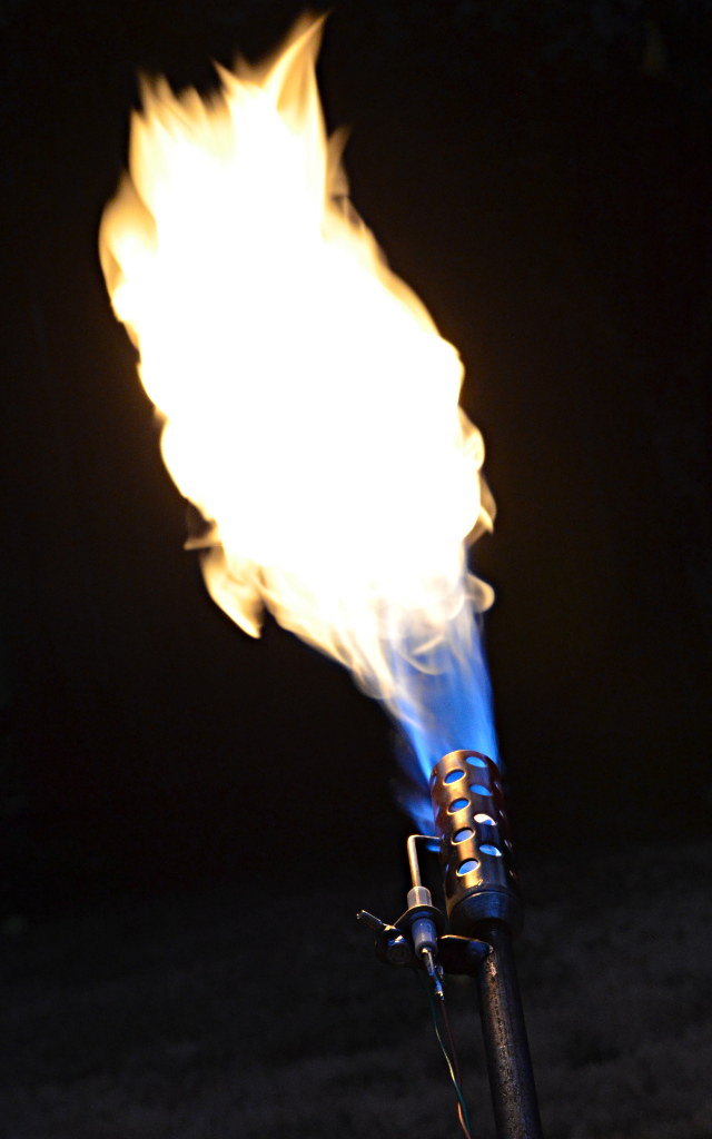
First Test With Fire
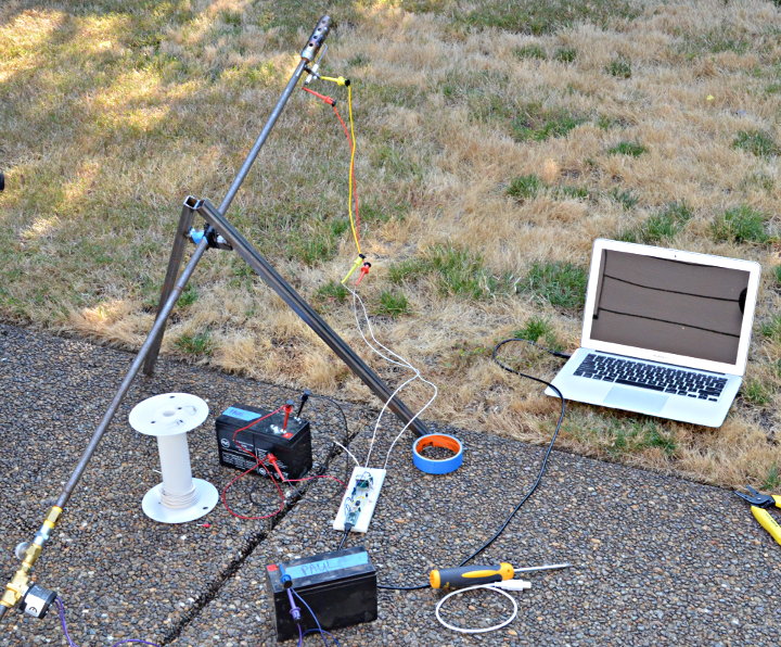
No amount of testing with resistors and diodes could really satisfy my lingering doubt. Would this would really work with actual fire? So it was time to run a first test with the breadboard circuit connected to a real flame.
Martin came over and we ran it for the first time with real fire. The Teensy had just a simple program measuring the elapsed microseconds for the capacitor to charge to 2 volts.
I’m happy to say the flame gave a really strong signal. I had done a lot of testing with 10M to 35M resistors. Even with the gas turned down very low, with the flame just barely flickering, we got readings (low numbers) printing in the serial monitor.
With the circuit working, it was time to turn it into a usable design to control the pilot light and other valves.
Circuit Board
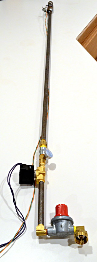
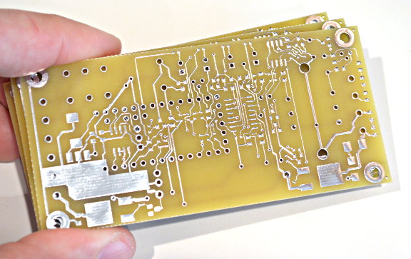
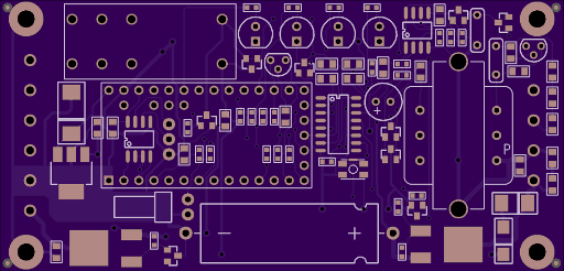
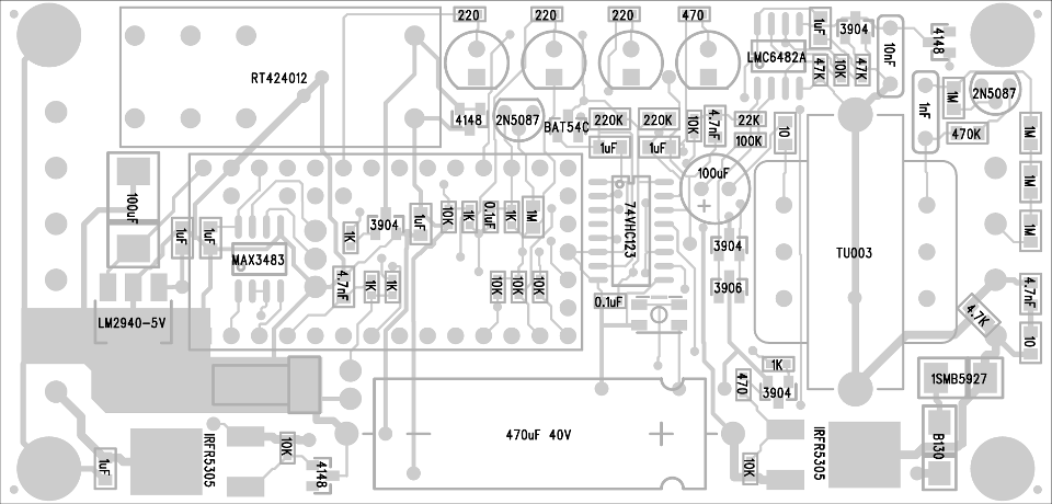
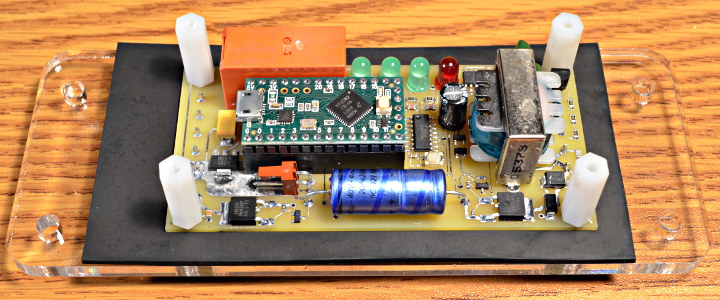
I quickly designed a circuit board with the flame sensing circuit, a power mosfet for controlling the pilot light gas valve, a relay to enable the other valves, a special timer circuit I’ll describe in more detail in the next section, and all the usual power input conditioning you’d expect.
Since time was running short, I ordered boards from Sunstone Circuits. They have a very rapid service. The quick turn prices are better if you choose the option for no solder mask or silk screen. I put the order in for these boards on Wednesday for a 2-day turn. Sunstone shipped 1 day early, so I actually got these on Friday! Thanks Sunstone. 🙂
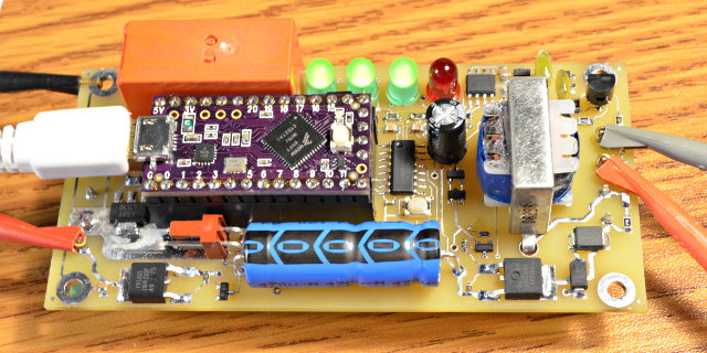
This was the first board I built. As you can see, it has a smaller transformer. I only had 4 of the larger, better transformers, so I wanted to try this one first.
Luckily, the board worked. No major mistakes. However, during testing I did discover one small oversight. The B130 clamping diode has a small leakage current. It’s nowhere near enough to turn on a solenoid, but it does make the output measure about 10 volts with a multimeter (having about 10M input impedance). On the final boards I added a 4.7K resistor, so the output is nearly zero volts when off. The rest of the info in this section has this extra 4.7K resistor added.
Here is the parts placement diagram for building the board.
When bringing up this board for the first time, there’s quite a lot of hardware to test. First, I applied 12V power without a Teensy installed, only to check the 5V power. If something is wrong with the power input, discovering it early can save the Teensy and most of the other circuitry.
I created this hardware test sketch to help verify most of the board’s hardware. While running, the gas solenoid output turns on for 1/2 second and then off for 1 second. It’s best to check the timing with a logic analyzer or oscilloscope, but if the timer circuity isn’t working the likely failures are no changes or 3 rapid pulses every 1.5 seconds.
Holding the pushbutton changes the output to the relay, to allow testing the other timer, the relay & its transistor, and of course the pushbutton.
The test program also generates a 1.2 volt AC waveform (3.3 volts peak-to-peak) at Teensy LC’s DAC pin. The opamp circuitry is supposed to increase it to 3.6 volts AC (10.3 volts peak-to-peak) at the transformer input. The transformer should step it up to approximately 40 volts AC (112 volts peak-to-peak on an oscilloscope). When testing these voltages, oscilloscope probes should be in 10X mode.
The final test to check the US5439374 flame sensor circuit was done with the board programmed with the final code. It prints the flame measurement to the Arduino Serial Monitor. Testing is pretty easy to do with resistors and diodes. A fast non-Schottky diode is best. I used a UF1003-T diode. Smaller numbers are stronger signal levels. The circuit should be able to measure at least 25M in series with the diode, but without the diode it should see no signal (highest number printed).
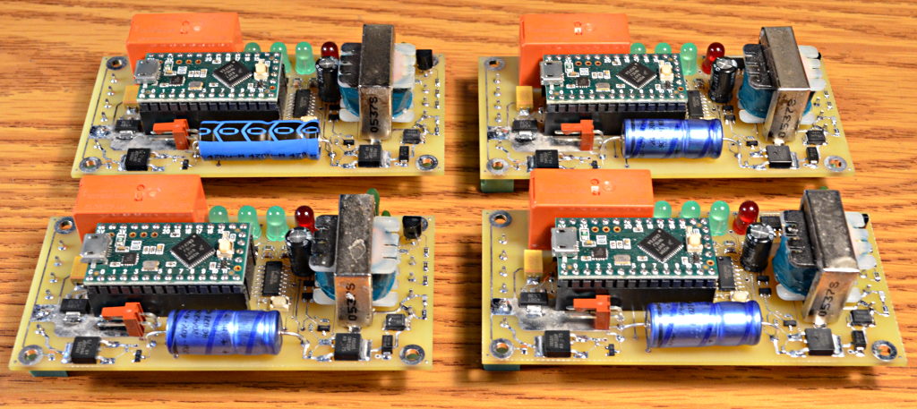
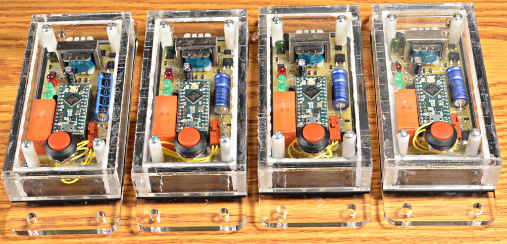
Building and testing these boards took most of a weekend. Here’s the final 4 boards.
Safety Features
The primary safety feature in Martin’s project is use of normally closed solenoid valves and plumbing rated for high pressure propane. All failure modes need to avoid keeping power applied to the solenoid valves. When the valves are off, the propane is contained.
Rather than allowing the Teensy pins to directly control voltage to the valves, I added hardware timers using a 74VHC123 chip. This part works essentially the same way as the familiar 555 timer chip, with voltage comparators and set-reset latches. But unlike the 555, it is designed to be retriggerable and it has logic for true edge triggering. These can be added to a 555 with extra parts, but each adds design compromises. The 74VHC123 gives both features in a highly reliable chip.
The timer turns on its output when it sees the rising edge of a trigger pulse. The edge trigger is important. Microcontroller failure modes tend to result in the pins stuck in one state. The timer does not respond to its input stuck high or low. Only the low-to-high transition begins the timing cycle.
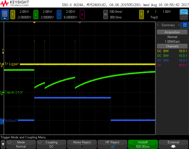
This oscilloscope screenshot shows the waveforms when running the hardware test program. The timer keeps it output high for 0.25 seconds following any rising edge trigger. The test gives 3 pulses, then waits. The waveform after this 3rd pulse tests a failure where Teensy might crash or lock up or otherwise fail. The hardware timer automatically turns off the propane solenoid valve after 0.25 seconds without another pulse.
The code Teensy runs also implements extra safety features. The main one is a count of good flame readings. Pulses are only sent to the timer if the previous 4 sensor readings all show a flame signal. While the US5439374 circuit works very reliably, this extra check is meant to have the gas turn off in the case where only intermittent measurements are made. Only when a consistent pattern of good flame readings are seen can the timers be triggered to turn on the outputs.
The code also measures the time while the manual start button is pressed. If this button were to fail (in the pressed state), and the pilot light is out, we don’t want to turn on any gas. A 20 second time limit is used, and it’s initialized to 100 seconds at startup. The manual start only works if the button is first observed as not pressed, to reset this time limit, and then can only keep the gas turned on for 20 seconds. If some unexpected mechanical failure results in an object falling onto the button, the worst case scenario is 20 seconds of pilot light gas.
Dust Resistant Construction
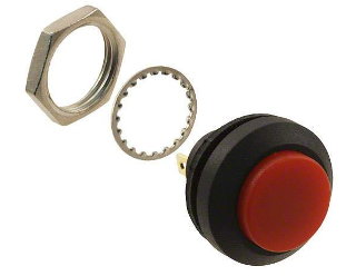
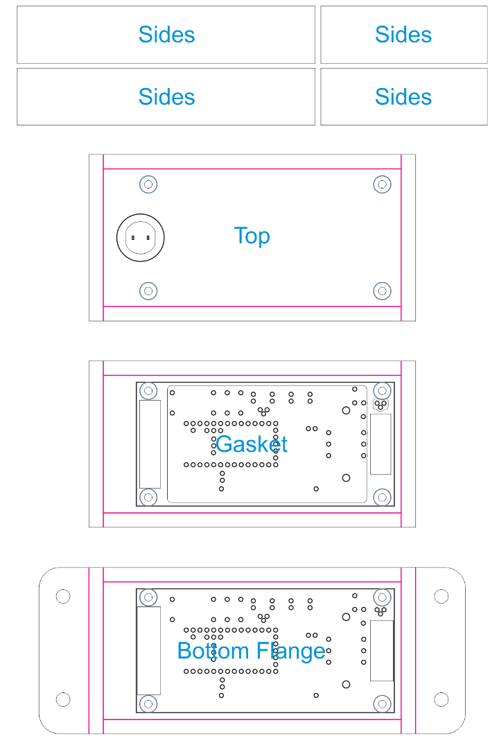
Anyone who’s been to Burning Man knows of the extreme dust. So I started the enclosure design around this IP67 rated pushbutton, which has real threads & a nut (so many are the flimsy press-in type).
This button photo is from the Digikey page, and really, I’m a bit curious how they manage to get such a perfect photos with the parts all standing? Must be tricks real photographers know…
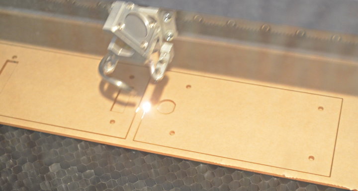
With the project coming together on a tight timeframe, I laser cut the enclosure from acrylic sheets I had on hand. Here is the lid made from thin material, due to the depth of the button’s threads.
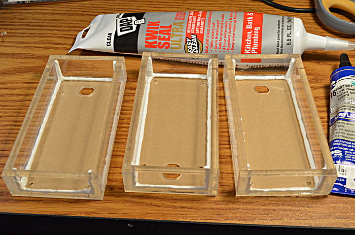
Some time ago, I purchased samples of rubber material to someday try to make gaskets for a waterproof box. This was the day…
Again, a real photographer could have probably captured this without so much blur. Maybe I could have with a tripod? Maybe not? The camera has a lot of trouble focusing on a black sheet.
Here is a first fit check of the gasket against an early attempt at the base.
One of the many little lessons I learned is the squeezed rubber exerts force against the plastic, enough to make it bend with this thin piece. I ended up discarding this part and cutting bases from the thicker material to (hopefully) avoid gaps from the base bending.
The gasket seals the lid against the base, and the PCB against the base where the 2 connectors fit. For the lids, I just glued pieces together with normal acrylic cement and then used silicone caulking compound along the inside seams.
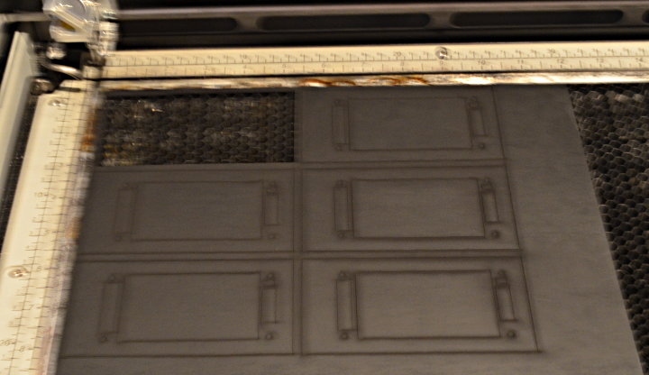
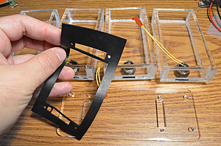
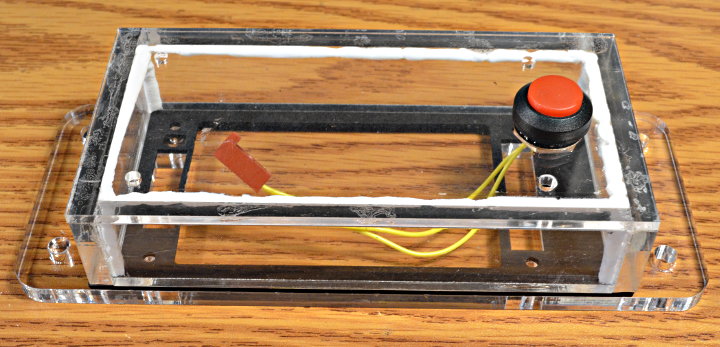
Here are the 4 completed lids with the buttons installed, and the final thicker base, ready to be assembled.
I’d like to remember this part of the project going smoothly, but the truth is I ended up making a few different base designs. Silly mistakes. Here’s the final fit check.
One other imporant piece was the height of these standoffs. The side walls are made to be about 0.015 inch taller than the combined standoff+PCB height, so there’s a slight squeeze applied to the rubber gasket.
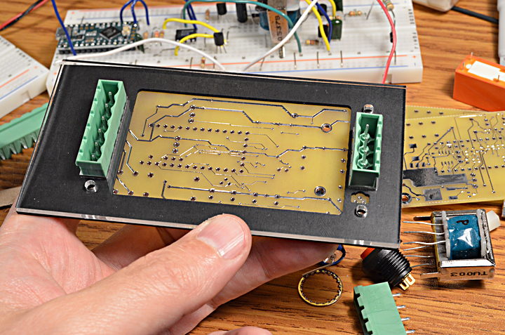
Here’s the final assembly with the screws. It stands off the table slightly, since the connectors protrude from the bottom. Maybe not the most conventional design, but this was done pretty quickly.
One thing I considered but didn’t do was buy special sealing machine screws. Hopefully the ordinary screws will work. I guess we’ll soon know if this design resists the Playa dust of Burning Man, though Martin will probably also end up installing these inside a box that offers another layer of protection.
Here is a list of all the materials I used to make these enclosures.
The laser cut design was create with Corel Draw v6. You can find the file flame_sensor.cdr in this Github repository for the code. These were cut with an Epilog laser, which has a driver that ignores the thicker lines when only vector cutting.
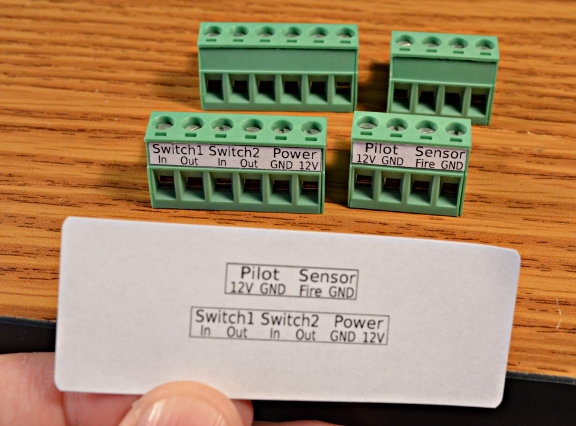
One final addition was printing these labels for the connectors. Troubleshooting electronics in the desert can be frustrating. Hopefully these will help a bit.
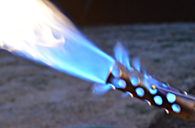
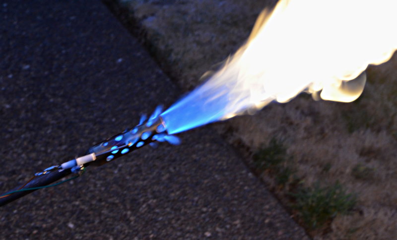
With everything built, we did another test with actual fire to make sure it really works. Throughout the latter part of this project I actually became pretty comfortable testing with the diode & resistors, which is very consistent and repeatable. But testing with the actual flame is fun.
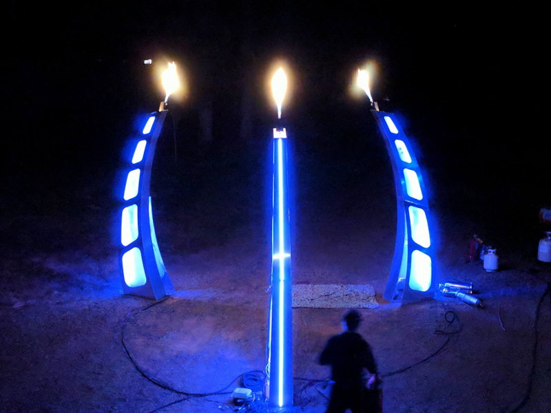
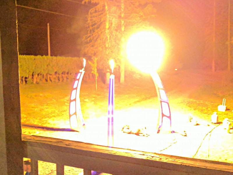
Here are the final assembled units, one for each of the Three Wishes, plus a spare.
I’m excited to see the Three Wishes project come together. I hope to update this page later with photos or a link to the project. Photos from first Three Wishes test added below.
If you do use any of this info in your own projects, please think carefully about safety and remember the disclaimer from above.
Three Wishes Art Installation Test (Aug 20, 2017)
Three Wishes photos by Jason Whitson, at Moltensteelman Headquarters, August 21, 2017.
Photo by Jay Bird, at Moltensteelman Headquarters, August 21, 2017.
Jon Watte (jwatte on the forum) built an autonomously navigating rover. This awesome rover is built for the outdoors and has individual steering on the 4 corner wheels. Not only can this impressive rover follow a track, but it can climb up stairs as well!
Moneypit V for Victory Autonomous Rover
Jon took it to a race early this month and placed 2nd out of 20! Way to go!