This tale begins with a customer reporting this cute little 2 port USB hub wasn’t working with Teensy 3.6.
In this article I’ll show how a protocol analyzer is used, how my instincts turned out to be very wrong, and along the way dive into arcane USB details you probably won’t see explained anywhere else.
First Instincts: Fail
This article is being written from the perspective of hindsight. You can much of the process as it actually happened on the forum thread where this problem was reported.
Most of my first troubleshooting instincts revolved around these 2 questions:
1: This hub works on Linux, Mac & Windows. What are they doing that Teensy isn’t?
2: All other hubs work on Teensy, so what’s different about this particular hub?
I believe most people would start with these 2 questions. In the end, both turned out to involve very wrong assumptions that were ultimately a distraction from finding the real problem.
Protocol Analyzer: Fail (Software Crash)
Usually the first step in debugging USB problems is to hook up the protocol analyzer. I have this one, the Beagle480 from Total Phase.
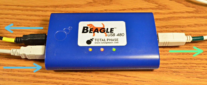
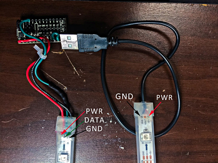
The way this works is pretty simple. On the left side where I drew the 2 blue arrows, your USB communication passes through. To whatever you’re monitoring, it just looks like a longer cable. But it makes a copy of all communication happening in either direction and sends it to the port on the right (green arrow).
If you’re just making a USB device that plugs into your PC, usually you can run software to capture the data from your PC’s driver. But when you’re making an embedded USB host like Teensy 3.6’s 2nd USB port, this is the only way to actually see what’s really happening. The downside is the cost. Total Phase sells this one for $1200.
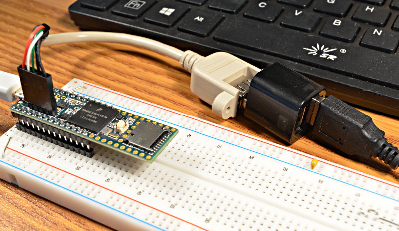
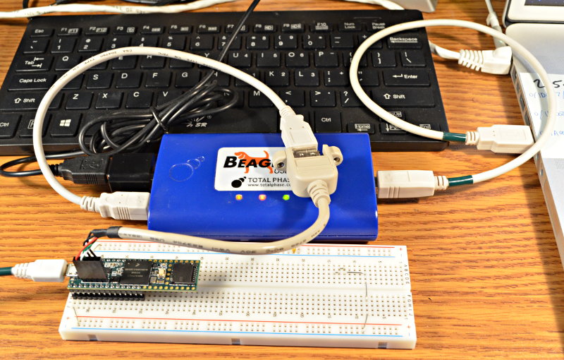
Here’s the test setup, with the Beagle480 inserted between the Teensy 3.6 and 2-port hub. Usually quite a clutter of cables is involved, but this little hub plugs right into the side of the Beagle480. The hub has 1 keyboard connected. A Mac laptop is watching the USB communication, and a Linux desktop is running the Arduino IDE to upload code to Teensy.
Despite the high price, it’s not made of magic. Inside it has a fairly small buffer memory. It has to send a copy everything on that right side port, which can be problematic during periods of sustained fast data flow.
This case turned out to be one of those problematic situations. Unfortunately Total Phase’s software does not handle this situation well. The Linux version simply crashes.
The Mac version is better. It hangs with the infamous Mac beachball. A Force quit is needed.
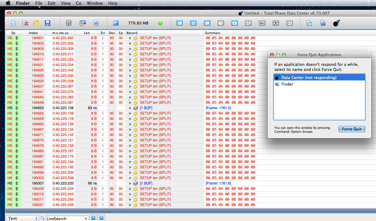
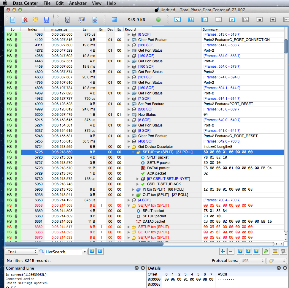
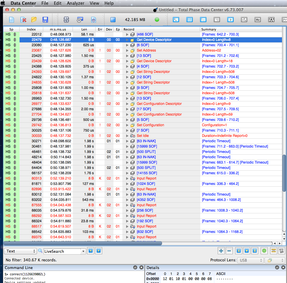
Fortunately having the software lock up means at least something can be seen on the screen, even if I could not scroll up to look at any other data. Whatever was going wrong with this hub was causing a SETUP token to be repeatedly tried. The timestamps show it’s happening about every 8 to 12 microseconds!
What’s Different About This Hub?
With the protocol analyzer not helping much, I decided to first focus on question #2. All the other hubs work. What’s different about this one?
In USBHost_t36.h on line 59 is an option to turn on lots of verbose debug printing. But it doesn’t print much about the USB descriptors. I decided this was a good time to fix that (rather than just plug into a PC and run a program to view), optimistically hoping the info would show some stark difference between this bad hub and all the good ones. I spent a few hours adding this code to print descriptor info.
Here is the configuration descriptor for this 2 port hub.
Configuration Descriptor:
  09 02 29 00 01 01 00 E0 01
    NumInterfaces = 1
    ConfigurationValue = 1
  09 04 00 00 01 09 00 01 00
    Interface = 0
    Number of endpoints = 1
    Class/Subclass/Protocol = 9(Hub) / 0 / 1(Single-TT)
  07 05 81 03 01 00 0C
    Endpoint = 1 IN
    Type = Interrupt
    Max Size = 1
    Polling Interval = 12
  09 04 00 01 01 09 00 02 00
    Interface = 0
    Number of endpoints = 1
    Class/Subclass/Protocol = 9(Hub) / 0 / 2(Multi-TT)
  07 05 81 03 01 00 0C
    Endpoint = 1 IN
    Type = Interrupt
    Max Size = 1
    Polling Interval = 12
Turns out this little 2 port hub is a Multi-TT type. I’ll talk more about the transaction translators soon. Most hubs have only a single TT, but 2 of my test hubs are Multi-TT. Here’s one of their descriptors.
Configuration Descriptor:
  09 02 29 00 01 01 00 E0 32
    NumInterfaces = 1
    ConfigurationValue = 1
  09 04 00 00 01 09 00 01 00
    Interface = 0
    Number of endpoints = 1
    Class/Subclass/Protocol = 9(Hub) / 0 / 1(Single-TT)
  07 05 81 03 01 00 0C
    Endpoint = 1 IN
    Type = Interrupt
    Max Size = 1
    Polling Interval = 12
  09 04 00 01 01 09 00 02 00
    Interface = 0
    Number of endpoints = 1
 Class/Subclass/Protocol = 9(Hub) / 0 / 2(Multi-TT)
  07 05 81 03 01 00 0C
    Endpoint = 1 IN
    Type = Interrupt
    Max Size = 1
    Polling Interval = 12
Turns out they’re an exact binary match, except for the last byte in the configuration descriptor. I can’t emphasize enough how this process involves looking stuff up in the USB 2.0 PDF, in this case page 266. This byte is just the hub telling the PC how much power is might draw. The 2 port hub say 01, meaning only 2 mA which can’t be right. But I know nothing in code on Teensy (which I wrote) ever look at this byte. Maybe someday we’ll detect power issues, but for now it’s ignored.
Hubs also have a special descriptor for their capability. It’s documented on page 417-418 of the USB 2.0 PDF. Here the 3 different hubs did differ.
2 port (not working)
09 29 02 09 00 32 01 00 FF


4 port, ioGear, GUH274 (works)
09 29 04 89 00 32 64 00 FF


4 port, no-name blue color, UH-BSC4-US (works)
09 29 04 E0 00 32 64 00 FF
While I now know these differences are meaningless, and really only the 3rd byte (the number of ports) matters, at the moment I found these it seemed like this just had to explain the problem. That 2 port hub is different.
Turns out the 4th byte describes features like which LEDs, over-current protection and other features the hub has. The 7th byte says how long we’re supposed to wait between enabling power and accessing a port, but the bad 2-port hub says only 1 ms, much less than the other 2 working hubs.
What Would Linux Do?
With nothing apparently different between the hub, I returned to the idea that Teensy must be missing some initialization or other step that hasn’t mattered for all the other hubs, but does for this one.
It’s easy to look at what Linux does, since nothing goes wrong that crashes the Beagle480’s software. Here’s most of the hub’s enumeration process on Linux:
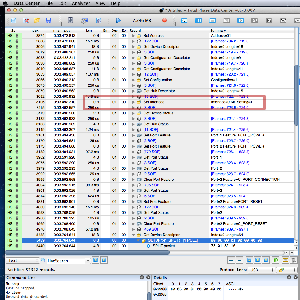
I quickly noticed Linux is sending this Set Interface control transfer. I did testing with all 7 of the hubs I have. This doesn’t happen on the USB 1.1 hub or the 3 that are Single-TT, but Linux does do it for all the Multi-TT hubs.
Adding this to the USBHost_t36 library took time. The hub driver was only looking at the first 16 bytes, to see if the interface and endpoint are compatible. I had to rewrite the hub driver to look for all the possible interfaces. Then when it was able to detect if 2 or more exist and parse which is the best to use, I added code to actually send that Set Interface command.
It didn’t make any difference. I’d poured a few more hours into coding, which in the long term was probably worthwhile, but still no closer to solving the problem!
Working Around Data Capture Software Lockup
I seriously considered resigning this problem to my low-priority bug list, since all the other hubs work. I considered restructuring the enumeration code to even more closely match Linux’s approach. I looked over the descriptor data yet again, hoping to find the answer, but no.
Clearly I needed to get around the problem with Total Phase’s software locking up. At first I just added a “while (1) ; // die here” right before calling new_Device() to start the enumeration process after the hub detects the keyboard. But that didn’t reveal anything useful.
I needed to let the problem happen, but then shut off the USB port before the Beagle480’s buffer could overfill (or whatever other problem causes the Total Phase software to lock up). Ultimately I did this:
    if (state == PORT_RECOVERY) {
        port_doing_reset = 0;
        print("PORT_RECOVERY, port=", port);
        println(", addr=", device->address);
static IntervalTimer stoptimer;
stoptimer.begin(panic, 1000);
        // begin enumeration process
        uint8_t speed = port_doing_reset_speed;
        devicelist[port-1] = new_Device(speed, device->address, port);
When I put in terrible debug code, I like to give it very odd indenting so I’ll see it when/if I later forget to remove it! In this case, a hardware timer is started to generate an interrupt in 1 millisecond, which calls panic().
The panic() function looked like this:
void panic()
{
    GPIOE_PCOR = (1<<6); // turn off USB host power
    Serial.printf("Panic stop\n");
    while (1) ;
}
With this I was finally able to see the beginning of the problem.
Somehow the bad 2 port hub was indeed working, at least for the first control transfer which reads 8 bytes of the device descriptor. But then everything goes wrong and nothing works. The host controller keeps trying to resend the Set Address command… at least for 1 millisecond, until the panic() function abruptly shuts off the USB port’s power.
Realizing What’s Really Wrong
I wish I could tell you there’s a reliable process to go from actually being able to observe the problem to understanding it. There isn’t!
In this case I spent several hours re-reading the USB 2.0 spec, staring at that screenful of info, and basically just guessing. For a while I considered there might be some sort of electrical interference problem unique to this hub, somehow triggered by completing that first transfer.
It literally took hours to focus on this 1 byte which turned out to be the cause of so much trouble.
To understand this byte, you need to know about USB split transactions, which are probably among the most arcane of USB features. This next part will be quite technical, so perhaps skip to the end if you’re not in the mood for intensely low-level USB protocol details.
Split transfers are used only between USB hosts and hubs. If you’re making a USB device, you’ll never see this type of USB communication. They’re used only when a host at 480 Mbit speed needs to communicate with devices at 12 or 1.5 Mbit.
When USB 3.x is used, all the 5+ Gbps communication happens on dedicated wires. The cables & hubs have a redundant 480 Mbit path. When you use a 12 or 1.5 Mbit device on a USB 3.0 hub, that slow communicate is done using split transactions on the 480 Mbit line. Slow speeds are never translated to the 5 Gbps lines.
USB has a lot of very specific terminology. From smallest to largest, communication is in Tokens, then Transactions, then Transfers. I’m not going into details here, other than it’s important to remember we’re dealing with 3 starts-with-T junks of data. Tokens are the smallest. Transactions are bigger, made up of Tokens. Transfers are the largest, maybe of of Transactions & Tokens.
These SPLIT tokens communicate with a Transaction Translator (TT) inside the hub. When the host wants to send a transaction at 12 or 1.5 Mbit, it sends a SPLIT-START token to the hub’s TT. If the TT isn’t busy, it acknowledges and begins working on the slow communication. That sequence of tokens is a transaction, also called split start (maybe confusing if you don’t know the context). Later the host sends SPLIT-COMPLETE. If the TT has finished, it replies with ACK, and if it’s still busy it replies with NYET.
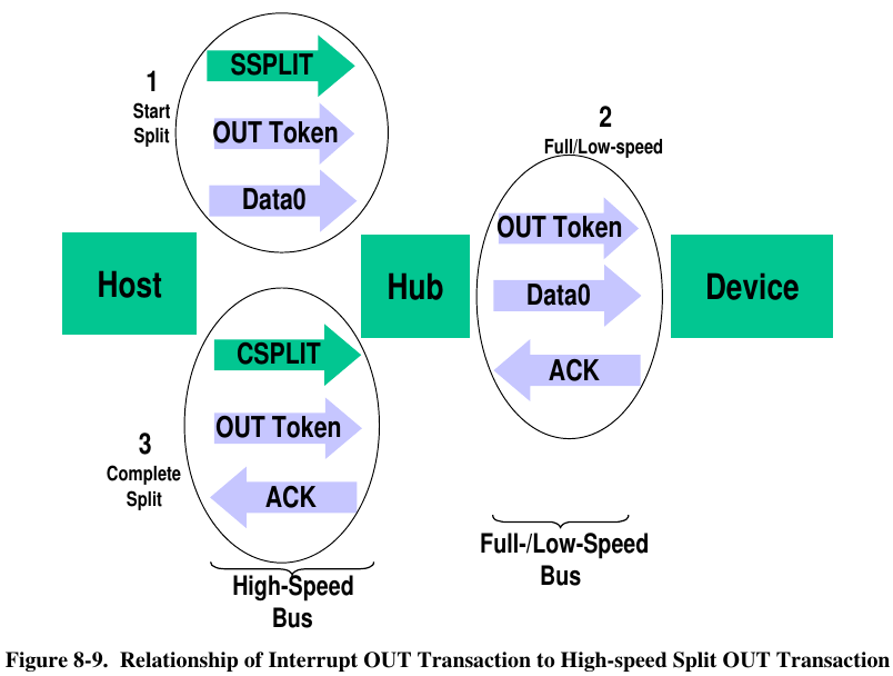
Here’s the diagram from the USB 2.0 spec on page 202 showing this for OUT transactions. Sadly there isn’t a diagram specifically for SETUP transactions, but my guess is this should be pretty close. Did I mention this sort of work is all about guesswork and re-reading technical specs over and over?
Total Phase’s software is very nice. It normally shows you one Transfer per line. If you want to see the Transactions that made up that transfer, you click the little triangle to expand. Likewise if you want to drill down to see the actual tokens, you can. Here’s the first successful transfer. Hopefully you can see this more-or-less corresponds to Figure 8-9, except SETUP instead of OUT. Of course, we only see the stuff from circles #1 & #3 since we’re connected between Teensy and the hub.
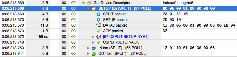
In this case, we can see Teensy sent 58 SPLIT-COMPLETE tokens while the hub slowly send that SETUP token at 1.5 Mbit to the keyboard, where the hub replied with NYET to the first 57, then finally an ACK.
This is important, because the process of figuring out why something isn’t working almost always involves first looking at the deeper details of what it’s supposed to do when it does work.
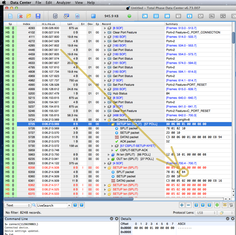
With that in mind, here’s an expanded view of the first Set Address transfer that fails.
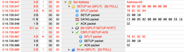
Remember the software is showing us nesting of Tokens inside Transactions inside Transfers. So the 3rd line is actually the first real data. This badness begins with the bytes 78 01 82 B4.
Earlier 78 01 82 10 was considered ok. But 78 01 82 B4. So what does that last byte mean? Again the answer is digging into the nitty gritty details in the USB 2.0 document. It happens to be on the same page as that diagram above.
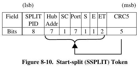
Even though going from 10 to B4 looks like a big change, in fact the top 5 bits are a CRC check which is expected to be totally different if any of the checked bits changed. So really this means just one of the “ET” bits flipped from a 0 to 1.
The meaning of those ET bits is documented a few pages later.
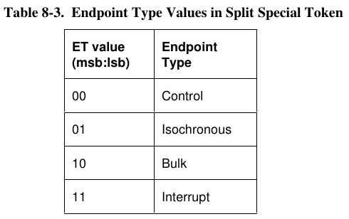
These bits were 00 for Control, but somehow became 10 for Bulk. That’s definitely not right! We’re sending a SETUP token, and that token has the endpoint number encoded within (also documented elsewhere in chapter 8….)
Where This 1 Bit Went So Wrong
The good news is this last part, going from an understanding of what’s wrong to finding the mistake causing it, is relatively easy. It took only about an hour. While I didn’t know exactly what controlled those ET bits, I was pretty sure it was something in the EHCI controller’s QH or qTD data structures.
USB controllers implementing EHCI are very unlike traditional embedded peripherals, where a handful of fixed register addresses control everything. EHCI gets almost everything from main system RAM, where it’s regularly using DMA to read linked lists and binary tree data structures to find out what work you want it to perform.
For each pipe/endpoint each USB device, you create a QH structure (except complexities for isochronous… but trying to keep this simple). Here’s the EHCI diagram for the QH structure.
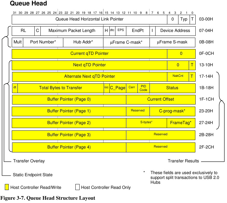
The first field is used for the linked lists or inverted tree pointers. The next two are where you actually configure how the hardware will communicate. The big yellow area is written by the hardware, coping other info there temporarily as it works on the Transfers you want. (Yes, the hardware deals in Transfers and automatically does the Transactions & Tokens)
While there’s a lot of small fields in those 64 bits, the “C” bit turned out to be the key. The EHCI spec documents it as:
Control Endpoint Flag (C). If the QH.EPS field indicates the endpoint is not a high-speed device, and the endpoint is an control endpoint, then software must set this bit to a one. Otherwise it should always set this bit to a zero.
Fortunately the code uses C structs to with distinctive names to represent the QH and other EHCI data structures. A quick grep of all the code turned up everything that accesses this field. Only a few of them actually write to it.
Ultimately the bug turned out to be just this 1 line function called pipe_set_maxlen()
pipe->qh.capabilities[0] = (pipe->qh.capabilities[0] & 0x8000FFFF) | (maxlen << 16);
Of course if you look at the 2nd line in the QH documentation, this is incorrectly zeroing too many bits, destroying the C bit and part of the RL field. It should be:
pipe->qh.capabilities[0] = (pipe->qh.capabilities[0] & 0xF800FFFF) | (maxlen << 16);
Indeed applying this fix made the “bad” 2-port hub work quite nicely.
Headslap Moment
After I found the fix, I looked one last time at the question “All other hubs work on Teensy, so what’s different about this particular hub?”
Here’s the communication with that keyboard through one of the “good” hubs!
Turns out the code has been sending improper SPLIT-START tokens all along, but every hub I own and the numerous hubs other people have used all were able to work anyway! The different was this particular hub was actually rejecting the bad tokens.
In all this time, developing this library earlier this year and all this recent work to track down this bug, apparently I never actually connected the protocol analyzer and watched the “good” hubs really communicating with low speed devices! Could have saved a *lot* of work. Now I know, in hindsight.