I recently obtained a new code signing certificate used to sign the Windows version of Teensy’s software. Because key storage rules have changed, and very little information currently exists for use in a cross compile workflow, I decided to write this article.
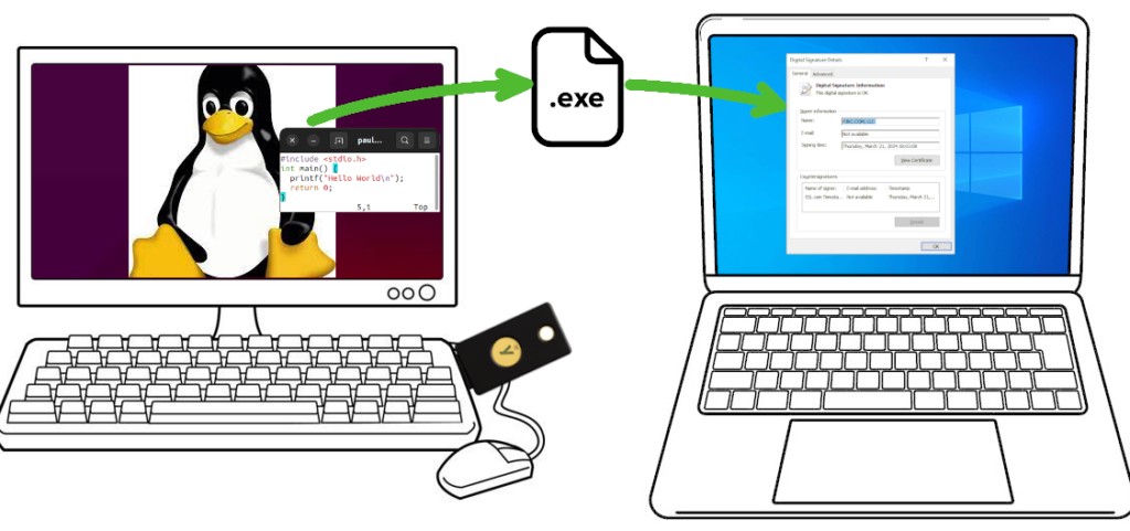
The basic concept is you wish to compile software for Windows, from the comfort of your Linux machine. The Windows EXE file needs to be properly signed, so users see “Verified Publisher” and Microsoft Defender SmartScreen will (eventually) learn your application is safe.
These steps were performed on Ubuntu 22.04. Other Linux distributions can very likely also work.
Buying a Code Signing Certificate
Before June 2023, obtaining a code signing cert was simpler and less expensive. You would create a private key and use it to send a certificate signing request (CSR). After verifying your identity, the certificate authority would send you the certificate file.
Signing a Windows EXE file requires these 2 items, a secret key and a certificate issued by one of the certificate authority companies Microsoft trusts. Previously it was just 2 files on your computer, or a single “P12” format file which can hold both.
Since June 2023, your secret key must either be stored inside a hardware token and/or stored on the certificate authority’s cloud service. Supposedly this is more secure.
It is also much more expensive! As with buying anything, shop around. Prices vary and change. As of March 2024, the best price I found was at SSL.com. This article isn’t sponsored or affiliated with SSL.com in any way. They simply had the best (least bad) price in March 2024. Pricing for “OV” was $110 per year for 3 years, and $250 for the hardware key. The actual hardware has $80 retail price when blank from Yubico.
If you choose another certificate authority, you might contact them to confirm the hardware key is Yubikey FIPS. Theoretically other hardware keys might exist, if not today then at some point in the future, and you would want to confirm whether the hardware they send works with Linux and libengine-pkcs11-openssl.
SSL.com also offers a cloud service which eliminates the need for a hardware key, but its least expensive tier is $20/month. That’s almost as much as the Yubikey FIPS hardware, repeated every year! Worse year, that low tier offers only 20 signatures per month. Teensy’s software has several signed EXE files. Merely building a few beta tests could mean needing the next tier.
After you’ve paid, the certificate authority will verify your identity. For “OV” level, the verification is so simple that the price and complexity of needing a hardware token feels rather wasteful. Nonetheless, to get Windows “Verified Publisher” this is the process.
Then all you can do is wait for your Yubikey token to arrive.
Collect Critically Important Data
Your Yubikey FIPS token will arrive initialized with 2 passwords, called PIN and PUK. Your first step is to obtain these 2 passwords.
From SSL.com, my Yubikey came with an 8 digit serial number, printed on a label and also on the key. On the SSL.com website order summary, under “CERTIFICATE DETAILS” -> “physical tokens” was an “activate” link. Clicking it brings up a dialog box to enter the 8 digit serial number. After entering the serial number, the PIN and PUK passwords appeared.
Other certificate authorities will likely work differently, but all Yubikey FIPS use these PIN and PUK passwords for access to the key. You must get the PIN and PUK passwords the certificate authority used. If the PIN is entered incorrectly 3 times, the key becomes locked. The PUK password lets you assign a new PIN password. If PUK is incorrect 3 times, the hardware becomes unusable! Make sure you have the correct PIN and PUK before using your key.
You will also need the certificate data. On the SSL.com I found this on the order summary page under “END ENTITY CERTIFICATES”. It begins “—–BEGIN CERTIFICATE—–“, has a couple dozen lines of base64 encoded data, and ends with “—–END CERTIFICATE—–“. Save this to a file. Any name is ok, I named it “mycert.pem”.
Install Software
Fortunately Ubuntu 22.04 has all the required software as packages. Use these commands install everything demonstrated in this article.
sudo apt install yubikey-manager osslsigncode ykcs11 libengine-pkcs11-openssl
sudo apt install gcc-mingw-w64-i686
sudo apt install wine
You only need the (large) wine package if you want to run your freshly compiled EXE on Linux.
Check Yubikey Hardware
Now you’re ready to plug in your Yubikey and check it. First run this command:
ykman listYou should see it detect your Yubikey and print basic info. The 8 digit serial number should appear.
YubiKey 5 NFC FIPS (5.4.3) [OTP+FIDO+CCID] Serial: 00000000Type this command to check the keys stored:
ykman piv infoYou should see results like this, but with actual serial numbers instead of zeros.
PIV version: 5.4.3
PIN tries remaining: 3/3
Management key algorithm: TDES
Management key is stored on the YubiKey, protected by PIN.
CHUID: 0000000000000000000000000000000000000000000000000000000000000000000000000000000000000000000000000000000000000000000000
CCC:   No data available.
Slot 84:
        Algorithm: ECCP384
        Subject DN: CN=SSL.com Code Signing Intermediate CA ECC R2,O=SSL Corp,L=Houston,ST=Texas,C=US
        Issuer DN: CN=SSL.com Root Certification Authority ECC,O=SSL Corporation,L=Houston,ST=Texas,C=US
        Serial: 00000000000000000000000000000000000000
        Fingerprint: 0000000000000000000000000000000000000000000000000000000000000000
        Not before: 2019-03-07 19:35:47
        Not after: 2034-03-03 19:35:47
Slot 9a:
        Algorithm: ECCP384
        Subject DN: CN=PJRC.COM\, LLC,O=PJRC.COM\, LLC,L=Sherwood,ST=Oregon,C=US
        Issuer DN: CN=SSL.com Code Signing Intermediate CA ECC R2,O=SSL Corp,L=Houston,ST=Texas,C=US
        Serial: 00000000000000000000000000000000000000
        Fingerprint: 0000000000000000000000000000000000000000000000000000000000000000
        Not before: 2024-03-04 15:51:07
        Not after: 2027-03-04 15:51:07
The “PIN tries remaining” is particularly important. If you enter the PIN password incorrectly 3 times, the hardware becomes locked. Best to download the graphical YubiKey Managers software from Yubico’s website, and use it to set a new PIN with the PUK password. However, 3 wrong tries with PUK locks the hardware completely. Unlocking requires deleting the keys you paid $250 to get.
Compile a Windows EXE program
Create a file “hello.c” with any simple C program.
#include <stdio.h>
int main() {
    printf("Hello World\n");
    return 0;
}
Use these commands to compile and run the code.
i686-w64-mingw32-gcc -Os -s -o hello.exe hello.c
wine hello.exe
Check Yubikey PKCS11 module pathname
The default PKCS11 module pathname is /usr/lib/x86_64-linux-gnu/libykcs11.so
If you run Linux on hardware other than x86-64, such as Raspberry Pi, or if you use a different Linux distribution, the pathname may differ. On Ubuntu, you can use dpkg to see all the files the ykcs11 package installed.
dpkg -L ykcs11
ls -l /usr/lib/x86_64-linux-gnu/libykcs11.so
ls -l /usr/lib/x86_64-linux-gnu/libykcs11.so.2
ls -l /usr/lib/x86_64-linux-gnu/libykcs11.so.2.2.0
Sign your hello.exe file
To sign your freshly compiled EXE file, run osslsigncode with these parameters. If your PKCS11 module pathname is different, replace it as needed.
Replace XXXXXXXX with your PIN password. Remember, your Yubikey becomes locked after 3 wrong PIN password attempts!
rm -f hello2.exe
osslsigncode sign -h sha2 -pkcs11module /usr/lib/x86_64-linux-gnu/libykcs11.so -certs mycert.pem -key 'pkcs11:pin-value=XXXXXXXX' -ts http://ts.ssl.com -in hello.exe -out hello2.exe
If hello2.exe already exists, osslsigncode isn’t very smart and will show confusing errors. Best to make sure it’s deleted before running osslsigncode.
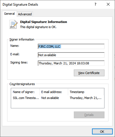
Your new hello2.exe file is a signed copy. When copied to a Windows computer, right click and view Properties. It should have a Digital Signatures tab. Clicking Details should show the signature info.
Microsoft Defender SmartScreen
Unfortunately, unless you purchased the most expensive “EV” type certificate, your signature using a brand new key will not yet have a reputation with SmartScreen. Windows users will see “isn’t commonly downloaded”.
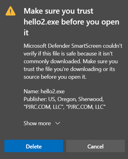
Eventually as more people download and use your software, SmartScreen will begin to trust it.
Feedback
If you have questions or feedback, please post on this forum thread.
Especially if you know of certificate authorities offers better prices, please share!
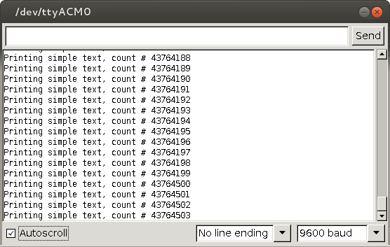
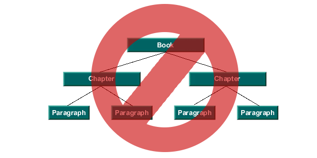
 The idea was simple. Since we only new add lines at the end, and delete the oldest lines from the beginning, this ought to be simple, right?