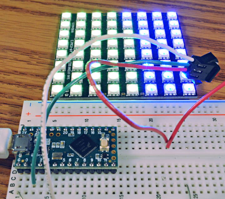
Last weekend I wrote a new WS2812 LED library featuring non-blocking performance.
A common problem with WS2812 / NeoPixel LEDs is creating their control signal with precise timing conflicts with other timing-sensitive software. Adafruit NeoPixel completely blocks all interrupts. FastLED can be configured to allow other interrupts, but any other library using interrupts for more than several microseconds can disrupt the WS2812 signal.
OctoWS2811 has offered non-blocking performance on Teensy 3.x since early 2013. But it consumes 8 pins and places restrictions on 1 or 2 others, which makes it difficult to use in many projects needing some of those pins. OctoWS2811 is designed for large LED projects (500 to 6000 LEDs), which is “overkill” for many projects using only dozes or even a few hundred LEDs.
Especially for projects using NeoPixel products with the Teensy Audio Library, or trying to receiving incoming serial data (especially DMX lighting control), we have long needed a simple, single-pin, easy-to-use library that doesn’t interfere with interrupts. For a long time I’ve meant to write this library, and this recent forum conversaton finally gave me the push to get it working to truly solve the NeoPixels+Audio isssue!
Inverted Serial Transmit
WS2812Serial uses one of the hardware serial ports to actually transmit the Ws2812 data. This idea certainly isn’t new. This message is the oldest reference I could find of the basic idea.
The serial port is configured to run at 4 Mbit/sec, which is exactly 5 times the 800 kbit/sec speed WS2812 LEDs expect. Every 5 data bits becomes one cycle of the WS2812 signal.
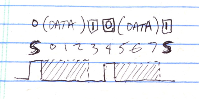
Standard 8N1 format serial sends 1 start bit, 8 data bits in least-significant-bit-first order, and then 1 stop bit. In this case, the signal is inverted from the usual TTL level output. Teensy LC & 3.x have hardware built in to invert the signal.
Since the start bit is always high, to send a zero bit to WS2812 the first 4 data bits are configured low. To send a one bit, the first 3 are configured high and the 4th low. The other half of the byte becomes the next WS2812 bit. Bit 4 must always be high, and bits 5 to 7 control the data seen by WS2812. The stop bit is always low, which automatically completes the 2nd WS2812 data.
Originally I tried using only 3 bits per WS2812 time slot, with 2.4 Mbit/sec serial baud rate. Many of the WS2812 datasheets say the timing allows up to 450 ns pulse width, so in theory this 417 ns pulse should work. In practice it did work with some WS2812 LEDs, but not others. In the end, I changed to 4 Mbit/sec which allows it to work with all WS2812 / NeoPixel LEDs.
Direct Memory Access (DMA)
To achieve non-blocking performance, and to run efficiently at 4 Mbit/sec baud rate, DMA is used to copy the data directly from memory to the serial port.
The result is a perfectly continuous WS2812 output which does not require any interrupts and leaves the processor free to run other libraries or your program to compute the next frame of LED data.
The need to compute all of the serial data before each update does lead to the one major drawback of this non-blocking approach: memory usage. Normally with FastLED or Adafruit NeoPixel, only 3 bytes of memory are used per LED. WS2812Serial requires 15 bytes, the normal 3 for drawing, and 12 for composing the serial data.
Fortunately the code is fairly simple. Here is the entire show() function which updates the LEDs. In the middle you can see “x = 0x08” which sets the begin bit for the 2nd half of each byte’s WS2812 output, and then the two logical OR operations which control the groups of 3 bits which are the shaded portion of the drawing above.
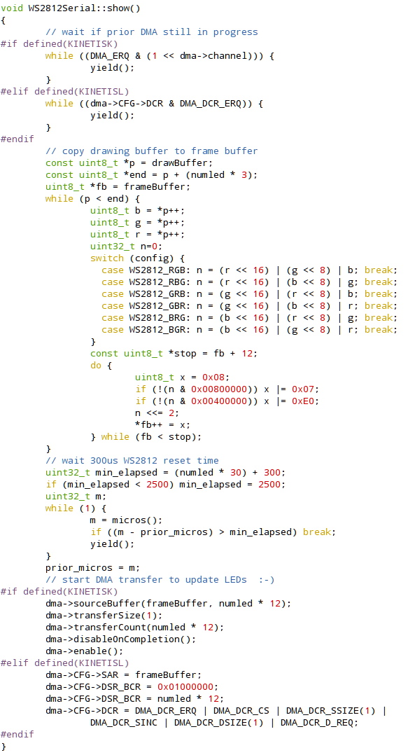
In this code sample you can also see my DMAChannel.h abstraction layer for DMA transfers. It is my attempt to make DMA simple to use, like other Arduino libraries. Obviously things are not quite there yet, especially for Teensy LC where you can see I had to resort to directly programming the DMA controller registers, rather than using the functions to configure the source, destination, transfer size and count.
At some point I intend to write a detailed article about how DMA works. Mike from Hackaday has been asking me to do this for years! If you’d also like to see it, remind me too….
One other possible idea for this library might involve using two DMA channels and their interrupts, to allow a smaller serial buffer. The basic idea would involve rendering only part of the output, and configuring each DMA channel to send half. Each each completes and generates an interrupt, another chunk of the output could be generated and the just-finished DMA channel could be quickly reconfigured to send the next chunk. Ideally, this could allow a relatively small memory buffer. It would require interrupts, but if they are delayed by other libraries or code, hopefully a user could make a trade-off between memory usage and allowable interrupt latency.
For now, WS2812Serial simply requires a big frame buffer and gives completely non-blocking performance. No interrupts are ever used. That does consume extra RAM, but the huge benefit is compatibility with other code or libraries require interrupts or CPU time while the LEDs update.