The balloon is filled with helium and is equipped with cameras, and iridium satellite modem, a Teensy using Mikal Hart’s GPS code, and a. The balloon achieved and altitude of about 35 km and captured video showing the beginning of the black of space. The payload was recovered using the iridium tracker.
Some time ago, I needed to actually “see” a current waveform in the 100 uA to 5 mA range with at least a couple MHz bandwidth. This extremely expensive probe would have been perfect, but instead I built something similar for about $30 using the amazing Analog Devices AD8428 amplifier.
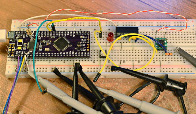
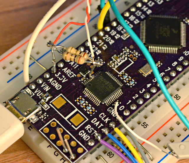
The first step was cutting the power trace and adding a resistor. I used two 1 ohm resistors in parallel.
At 5 mA, this makes only 2.5 mV. My scope’s supposed resolution is 1 mV, but the truth is there’s plenty of noise down in the 1 mV range. That’s pretty common for most scopes, even pretty spendy ones. So it’s just not feasible to measure this signal directly (not to mention using 2 probes and subtracting them in the scope).
That incredibly expensive Agilent probe probably has a couple really nice amplifiers inside…. so I went searching for an amplifier. After a bit of searching, I found the AD8428. It has a fixed gain of 2000 and a bandwidth of 3.5 MHz. That’s a gain-bandwidth product of 7 GHz !!! It’s also an extremely well matched instrumentation amp with an amazing CMRR of 140 dB. So it gets rid of the power supply voltage and outputs the amplified signal referenced to ground.
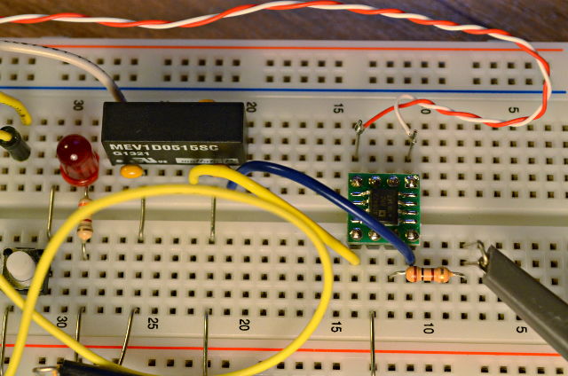
The AD8428 is perfect. It’s so very easy! Of course, such amazing performance costs money: about $20. Here’s that expensive little amplifier, and a 5V to +/- 15V power supply (about $10) to power it.
The one trick with measuring such tiny voltages is twisting the 2 sense wires together. Honestly, I didn’t try it running them separately, but since this thing is getting voltages in only the microvoltage range for the lower measurements, I didn’t want to risk picking up noise. I also put a 100 ohm resistor on the output, just in case I accidentally short the output or do something clumsy that might blow that little $20 part.
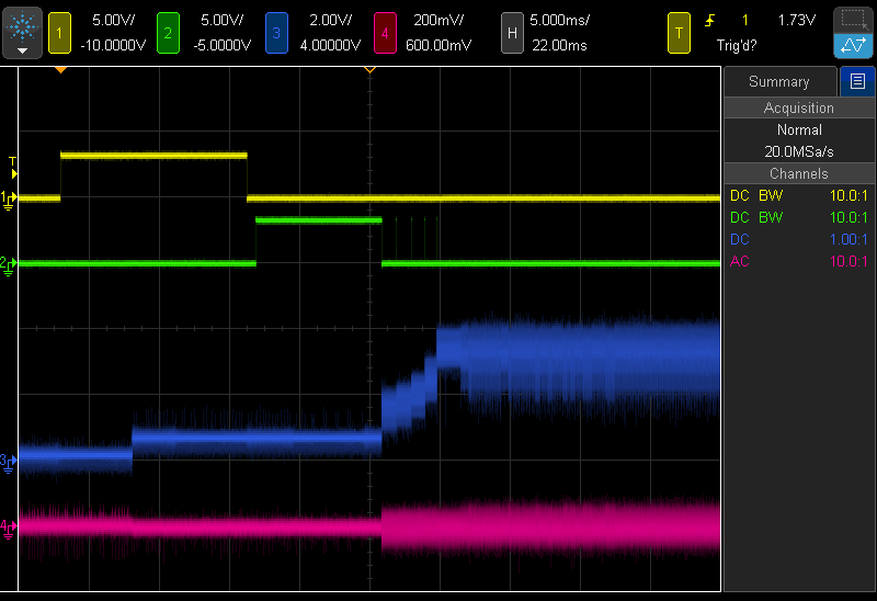
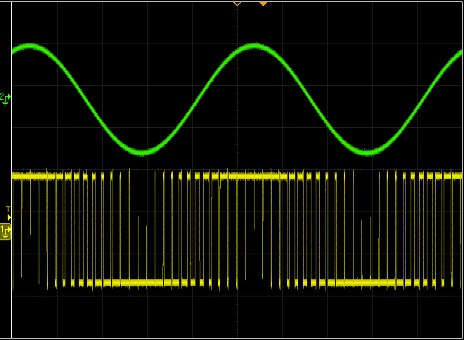
Here’s a scope screenshot using this little amplifier to “see” the current (the blue waveform).
In this test, the microcontroller is running in its slowest mode at only 10 kHz, drawing about 120 uA. Then when the chip’s internal oscillator is started, the current jumps to about 600 uA. Later, the CPU switches to actually clocking from that oscillator. There’s an on-chip clock divider which is switched in and increased gradually.
The bottom trace (red) is the voltage on the chip’s 1.8V linear regulator. It turns out that sudden jumps in current cause pretty substantial downward spikes on the regulated voltage. This more gradual startup approach really helps. This sort of thing is impossible to see with a slow multimeter, but with a reasonably good bandwidth measurement of the current, it’s easy to see what various code actually does to the current.
I tried connecting my multimeter to the amp output. Sometimes it’s just a lot more convenient to look at a single number on a meter than fiddle with the scope. I had been using the current mode on the meter before building this. One thing I was surprised to find it my little meter updates its screen much faster while measuring about 125 mA than it does when measuring 125 uA.
Another interesting thing I’ve been noticing is patterns within the blue current waveform. This Agilent scope has a “digital phosphor” rendering of the huge amount of data it collected. This static screenshot can’t really capture the interactive experience of adjusting the waveform intensity, where various regions within the data change brightness differently, indicating there’s something interesting/different going on. Even so, you can see several areas in the screenshot where interesting things are happening once the CPU is up and running. It’s interesting how the current waveform changes as different code executes.
I know this isn’t anything terribly impressive… basically just buy a high-end amplifier and use it with a series resistor. Maybe it even reads like an Analog Devices ad? I’m not affiliated with Analog Devices… I just bought this part at normal qty 1 pricing from Digikey.
Still, this is the first time I’ve ever really looked at such low microcontroller currents with a few MHz bandwidth, and I’m guessing not many people have ever bothered to really measure such currents, so I thought I’d share.
Years ago I originally posted this article to the DorkbotPDX site. Hackday published an article about it at the time. Since then, the DorkbotPDX blog section has vanished. I’m reposting it here, to preserve the info… for the next time I or others might need to do this sort of current measurement on a budget.
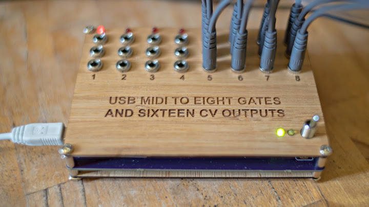
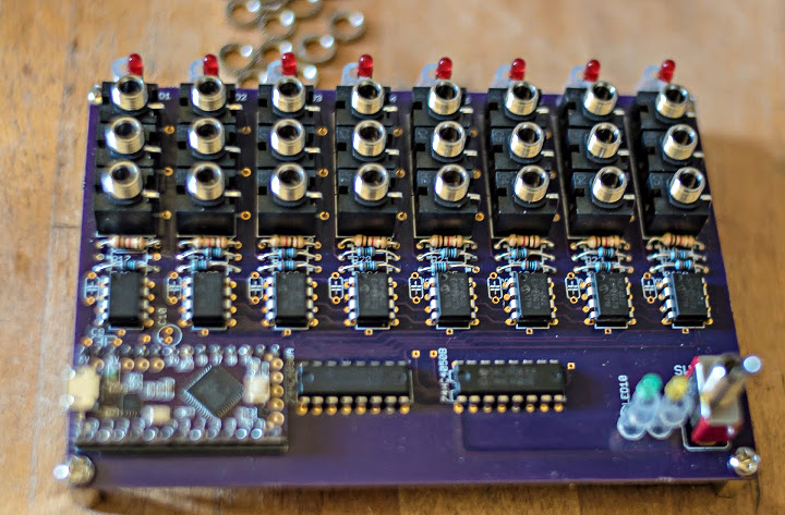
The control voltage (CV) outputs are 12-bit and 0V to 4.096V in range, with a four octave range for pitch.
The device has 3 mapping modes – 0, 1, and 2.
In mapping mode 0, gates 1 to 8 respond to note on and note off messages on MIDI channels 1 to 8. CV outputs 1 to 8 are determined by the pitch of note on messages on MIDI channels 1 to 8. CV outputs 9 to 16 are determined by the velocity of note on messages on MIDI channels 1 to 8.
In mapping mode 1, gates 1 to 8 respond to note on and note off messages on MIDI channels 1 to 8. CV outputs 1 to 8 are determined by the pitch of note on messages on MIDI channels 1 to 8. CV outputs 9 to 16 are determined by the control change message for controller 1 on MIDI channels 1 to 8.
In mapping mode 2, gates 1 to 8 respond to note on and note off messages on MIDI channels 1 to 8. CV outputs 1 to 16 are determined by the pitch bend value of pitch bend messages on MIDI channels 1 to 16.
The 16′ x 8 ‘ wall is made up of 10 4′ x 4’ panels. It has a Teensy 3.2 driving 2560 WS2811 LEDs and uses the FastLED library, ARTNET/DMX protocol, and Jinkx 2.4 software. For power they used 5V 30 Amp switched-mode power supplies (SMPS) for every 512 LEDs.
Loyal J made a cool USB pinball controller, Pinbox Jr, to use on your PC.
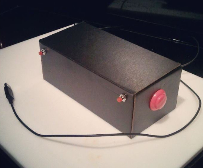
The Pinbox JR is a USB controller that gives PC games the feel of playing on a real pinball table. It interfaces with a PC as a USB keyboard and maps the pinball buttons to various keys on the keyboard. The latest version of the Pinbox Jr includes an accelerometer to simulate the tilt feature if you shake the controller.
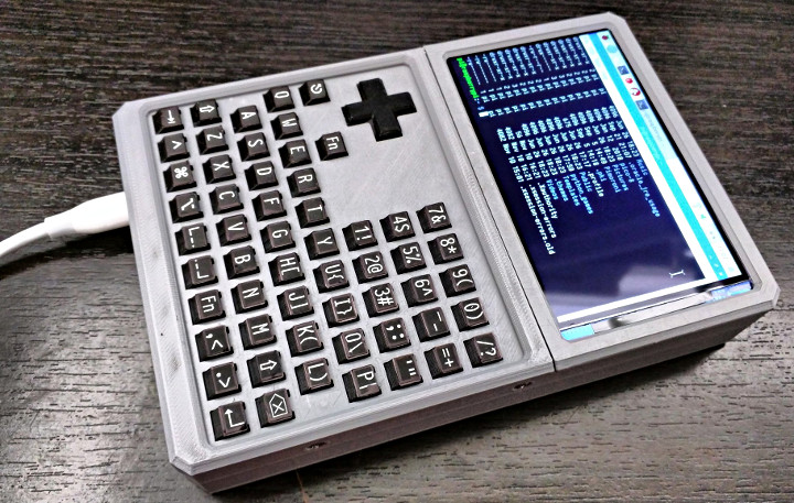
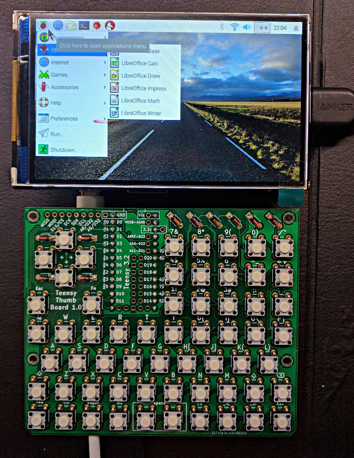
This small tactile keyboard is super to use with handheld projects. It has 60 keys arranged in a QWERTY layout and number keys arranged in a number pad layout. The board has beginner friendly through hole soldering with a Teensy, 60 pushbuttons, and 10 zener diodes.
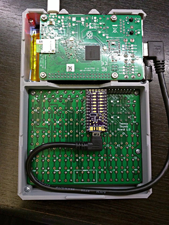
Anthony used this thumb board to make a handheld Raspberry Pi. Using the Teensy he was able to add backlight control and low batter monitoring in addition to controlling the keyboard.
Code for the project can be found in the Teensy Thumb Keyboard Github repository. KiCad files are available or you can also order the PCB from Tindie. Finally, you can find the files to 3D print the case used for the handheld Pi project on Thingverse.
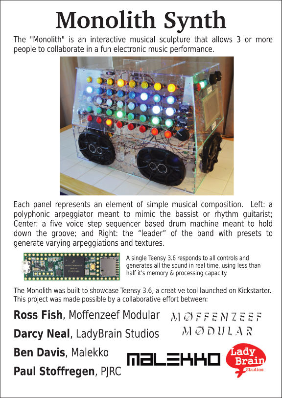
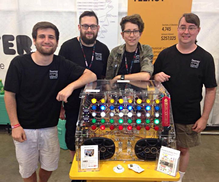
Ben Davis, Darcy Neal and Ross Fish collaborated with Paul in early 2017 this Monolith Synth. It was shown at Tested and the San Mateo Maker Faire.
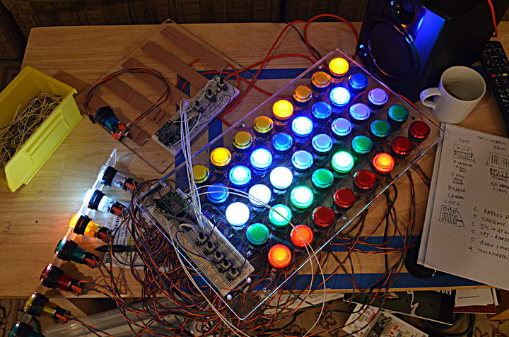
The Monolith Synth is interactive sound sculpture, with 40 “arcade” buttons on the front as a percussive step sequencer and 2 touch-sensitive side panels for direct performance.
Typical usage scene at Maker Faire, with kids and adults playing with it non-stop all weekend long.
This crazy adventure started with Kickstarter reached out to me, only 6 weeks before Maker Faire, looking to showcase 4 successful projects in their booth. They wanted to show “creative tools” and how people used them. So I reached out to a few synthesizer folks I’ve met and who’ve used Teensy. They also suggested bringing it to Tested to make a video. So it began…
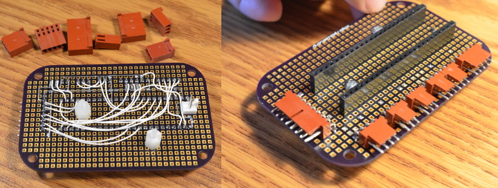
From the beginning I had a step sequencer using illuminated arcade buttons in mind. So I quickly designed this little I/O expander board and sent it off to OSH Park’s Super-Swift service.
The whole project came together over just 4 weeks. Our first meetup was just to discuss what to build, followed a week later by our first build night. By then the I/O expander boards had arrived. We made not the final Monolith, but 3 breadboard prototypes, so the software development side could begin!
Another meetup focused only on software. Almost all the software was developed on these prototype panels.
In this picture you can also see the panel layout sketches on the notepad on the right side, and a blue tape model underneath on the table, which we made to get an idea of the overall size.
Ross and Darcy had synthesis plans that needed a signal-controlled PWM waveform and improvements to the envelope feature, so I worked on improvements to the Teensy Audio Library while they wrote the Arduino sketch code.
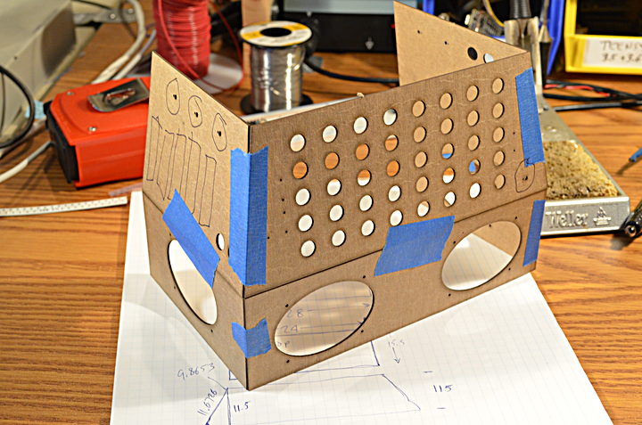
The day before our next meetup, I started turning those sketches into a design for the laser cutting. I made this 1/4 scale model of the front and side pieces. At this point, none of the back side or interior ribs (for strength) had been designed, and you can see the model lacks the many holes for screws & brackets which joined everything.
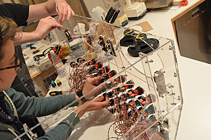
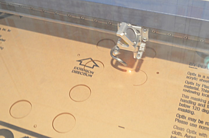
Only 2 weeks before Maker Faire we had an epic 13-hour build day where all the final parts were laser cut and assembled. Here’s a photo of Darcy & Ben putting the panels together on my kitchen counter!
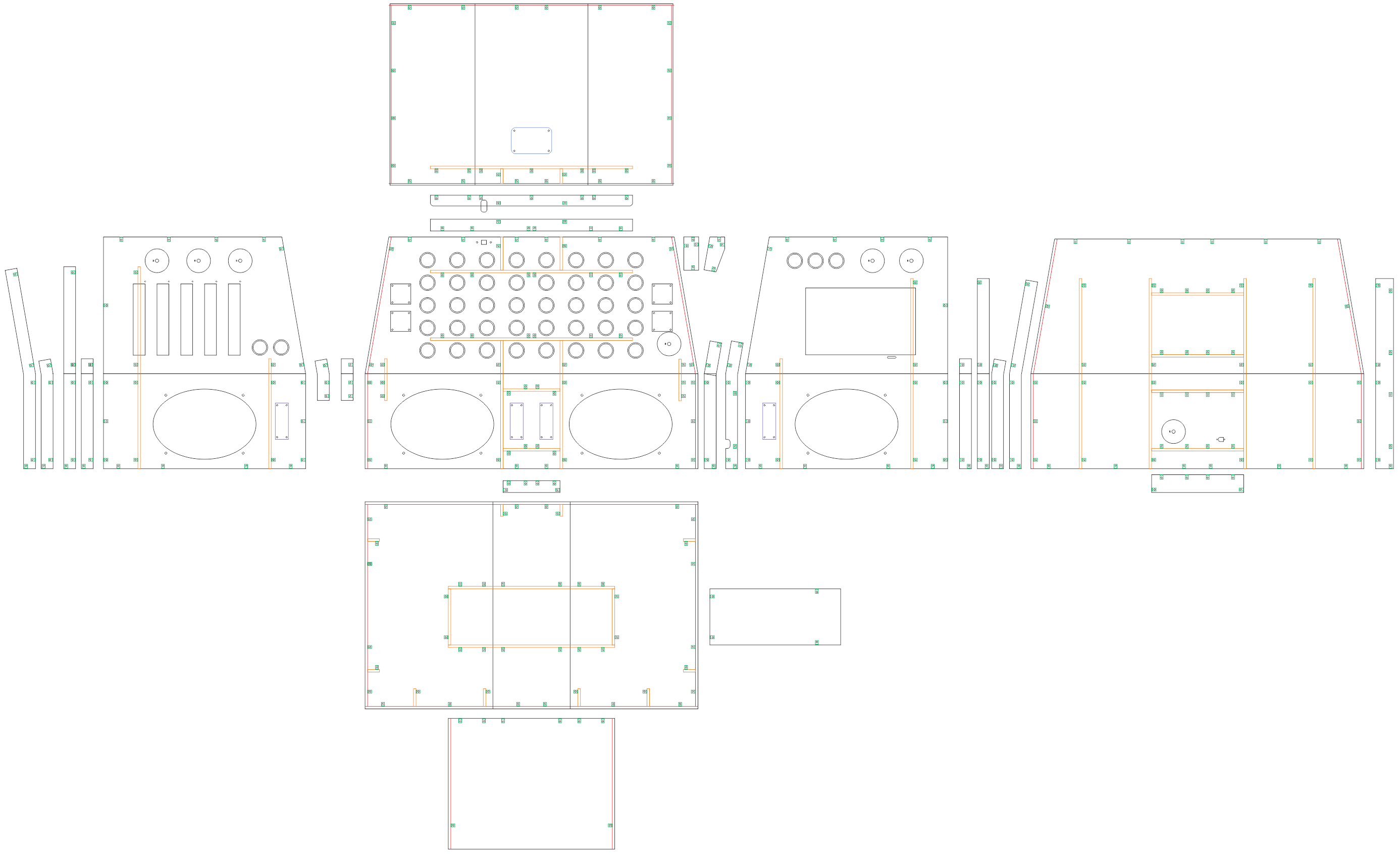
All the clear acrylic plastic parts were completely drawn, with all mounting holes, and made that day.
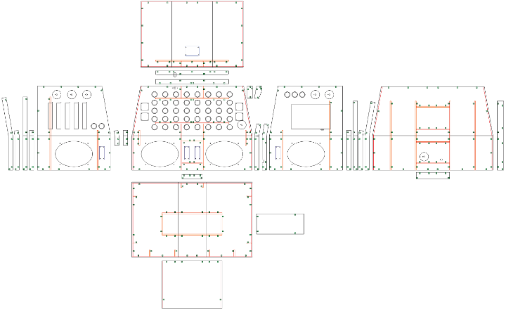
Here’s the complete layout of all parts (mk2017_design):
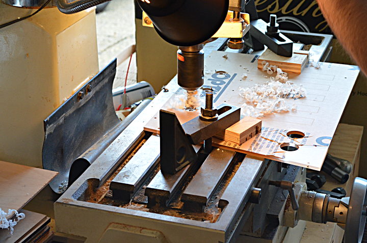
While the laser did most fabrication work, other steps like countersinking for the potentiometers were needed. It was indeed an epic 13 hour day of making.
A couple days later, I spent a whole day completing the wiring we couldn’t get done in those 13 hours. Erin Murphy (the “Soldering Goddess” at PJRC) put in a few hours on aesthetic improvements to the messy tangle of wires from so many buttons.
Just a few days later we had our last “build” session, to get the 3 separately written Arduino sketches merged and working together as one integrated project. Even though everything has been designed to go together, this session went very late. Ben did much of the heavy lifting to merge the 3 programs.
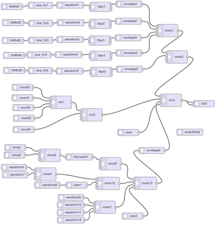
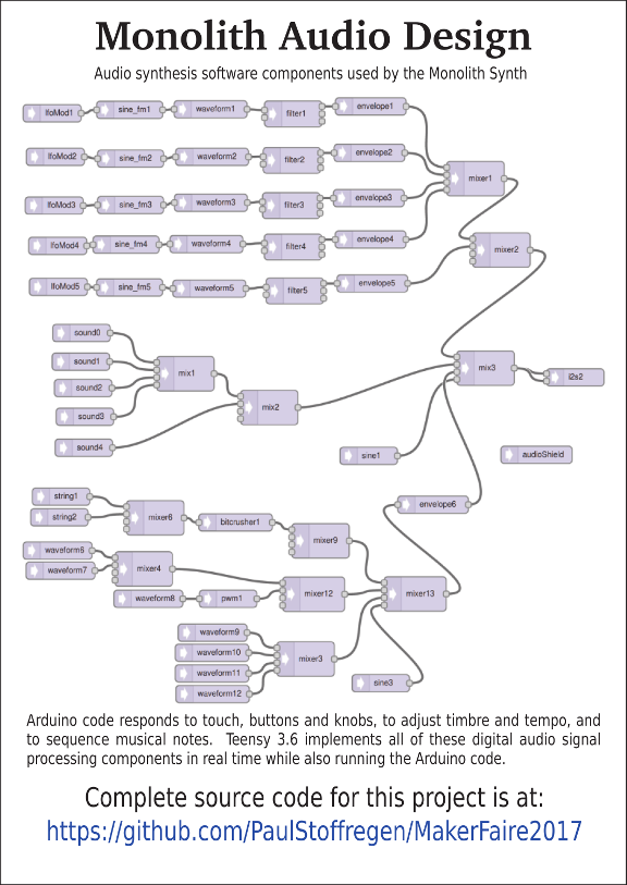
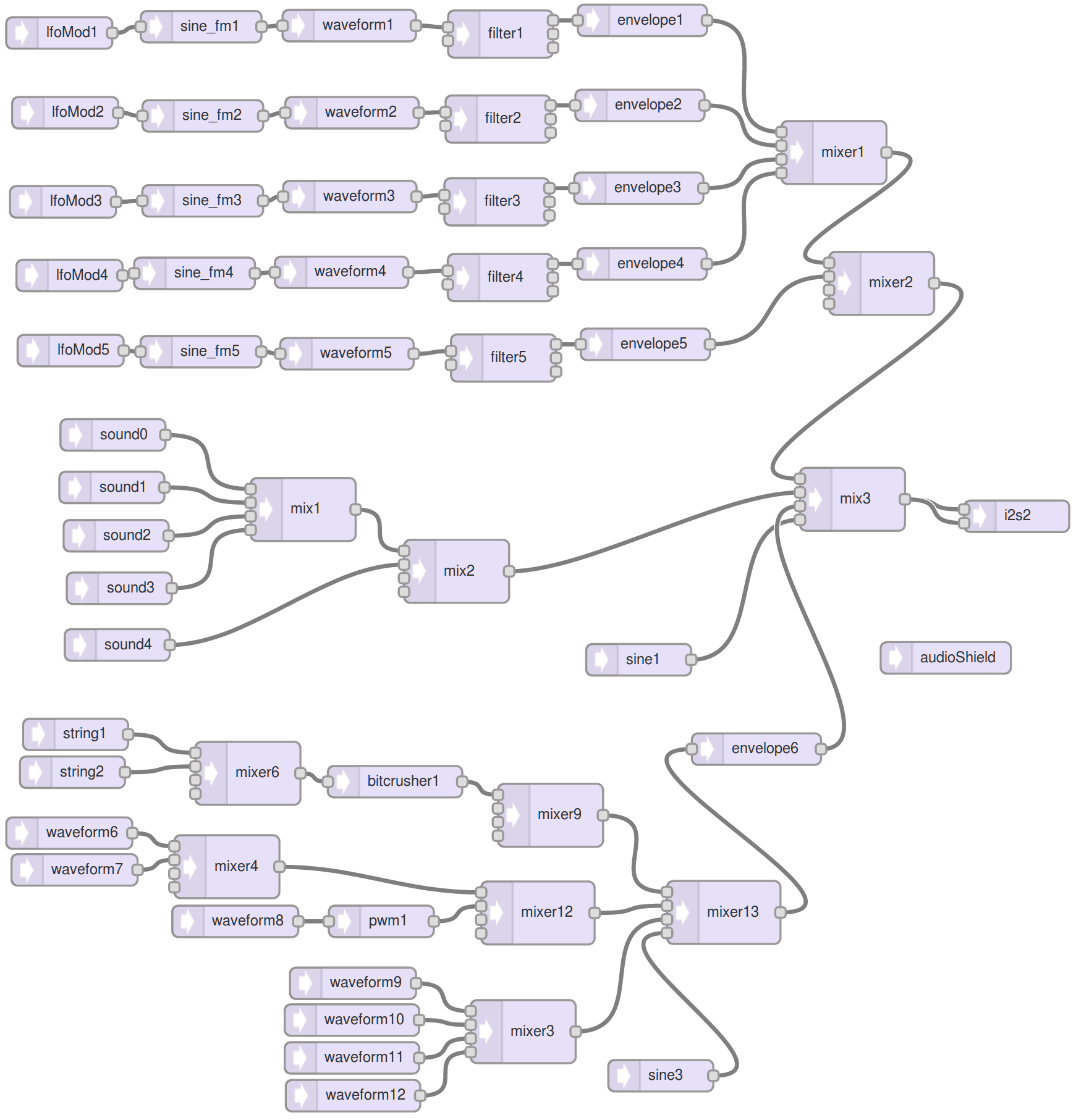
This is the final audio DSP system settled upon that late night.
This was the first actual usage of the Monolith, well past 1am when we finally had it all up and running.
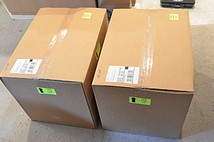
The next day I took it all apart and packed all the pieces and spare parts into these 2 big boxes, weighing in at 55 and 40 pounds!
This is the first time I’ve ever shipped a project to Maker Faire, rather than driving a truck or hauling cases of checked baggage on a plane. So much easier, and it allowed time to work on a nice handout card. After some back and forth with the others and last-minute proof reading by Robin, who caught what would have been embarrassing typos and grammatical errors, we sent this card off to be fast-turn printed.
Darcy and I flew to San Francisco early and spent the day with Tested, putting it back together while they shot that awesome video. Sometime I hope to have even 1/10th that sort of video production skill.
Since it was already put together, we had little to do setup-wise. Friday morning Ben, Ross and Darcy did some adjustments of the sound levels which really made it come to life in the space. For anyone who wishes to dig deeper into the technical details, the complete source code is available on Github.
During the 3 days of Maker Faire, things went very well. We did experience a couple minor issues. Massive electrical noise from so many other projects played havoc with the capacitive touch sensing. Saturday evening I rewrote the code to look for changes from an average rather than just an increase from a threshold, which allowed it to usually work well enough. The other tech issue was a bass. When turned up louder, the bass notes would shake all the plastic panels, rattling screws and even some of the connectors loose at time. Easy to fix.
Towards the end of Sunday, the Maker Faire folks came around and gave up an award. At first I shrugged it off, since they’ve done the same for other stuff I’ve brought in prior years. But those were the blue ribbons. Apparently the only hand out one of these red one each in “zone”. They said it’s a big deal…
Really, the best thing about this year was working with a great team. Ross, Darcy and Ben really stepped up and did a great job on so many parts.
Shortly after Maker Faire 2017, this article was posted to the DorkbotPDX website. Since that time, the DorkbotPDX blog section has vanished. We’re reposting it here, to preserve this project’s history. A copy of the original can also be found at the internet archive.
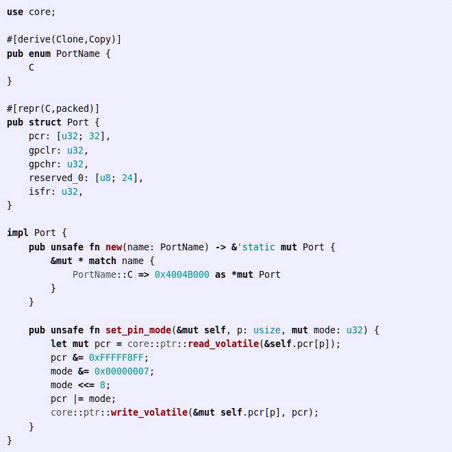
The tutorials are targeted at people who have a basic knowledge of Rust and “lightweight” embedded development experience. The first tutorial covers bootup of the processor to getting the LED to blink – with a good number of topics covered in between. Parts two and three go on to cover serial communication and hardware allocation. Each of the tutorials has quite a lot of information and detailed explanations of a number of topics important in embedded development. Overall this series is a great way to get going on programming Teensy using Rust.
Branan has indicated that the next tutorial in the series will cover DMA (Direct Memory Access) and interrupts will be in another upcoming tutorial
Update on the Teensy/rust stuff: DMA as a Future works! And I think I've convinced myself it's safe! I wanted to do interrupts, but I might save those for another post. That means I'm really ready to finish the prose and get it up!
Forum user Austin519 made a stylish, sound reactive LED light up coat.
The coat features 673 WS2812 LEDs driven by a Teensy 3.2, Prop Shield, and an ADMP401 MEMS microphone. It’s powered bu 2 5200mAh lipo batteries. It includes some user controls to change the pattern, sound reactivity, and overall brightness.
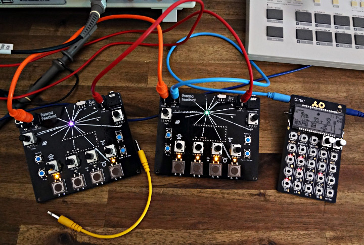
Tomash Ghzegovsky made a very cool DIY drum machine for the 2017 Fasma Festival
The goal of the project was to come up with something small, affordable, and buildable in just a few hours. The result was this portable, battery-powered drum machine.
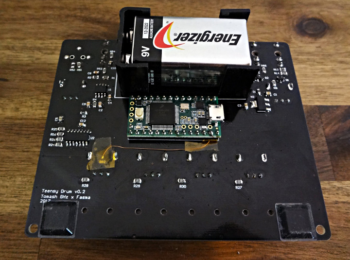
While this drum machine may be small in size, it’s not small on features. It has 4 voices (kick, tom, snare, and hat) and 4 parameter controls per voice – pitch, decay pitch modulation, and distortion. A 9V battery will power this little guy for up to 7.5 hours. More information on the features can be found on this GHZ LABS page.
Tomash put some great documentation together so that you can build your own. A manual, schematics, bill of materials, gerber files, and firmware are all available on this GitHub page.
