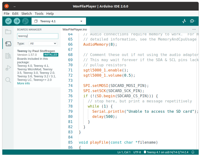
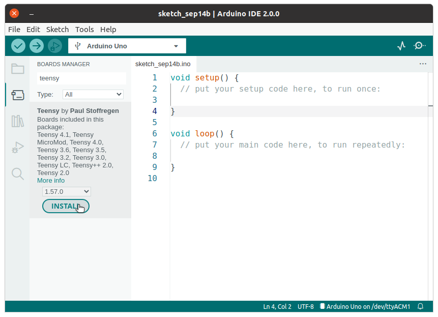
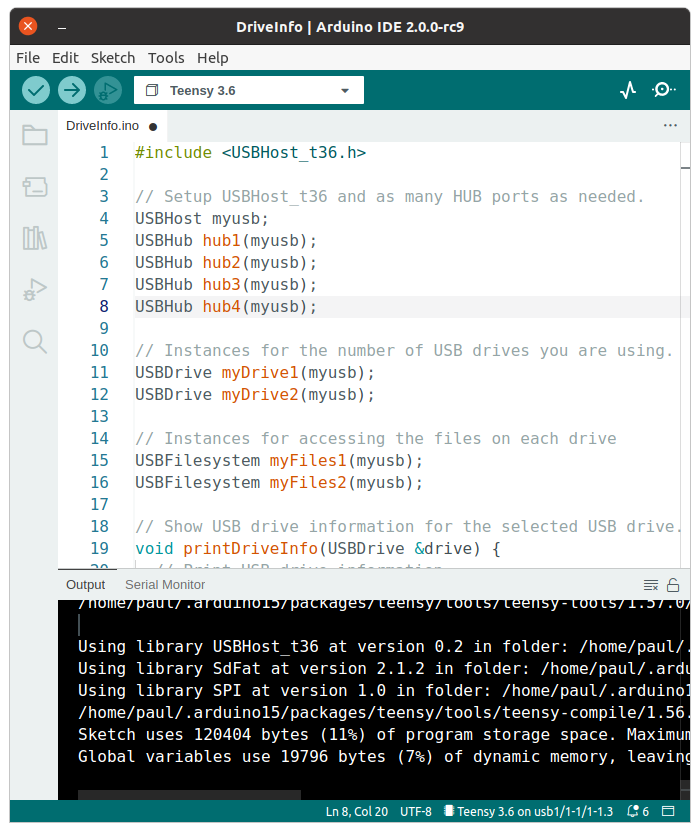
Teensy software 1.60 has been released. Arduino IDE 2 should automatically detect the new version and give a single click update.
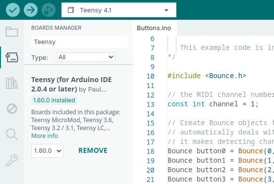
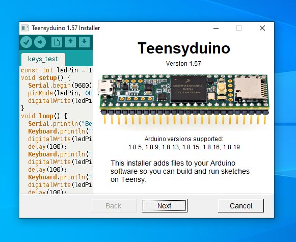
For Arduino IDE 1.8.x, you must download and run the special installer.
In this article we’ll take a quick look at the new features and many bug fixes and small improvements 1.60 brings.
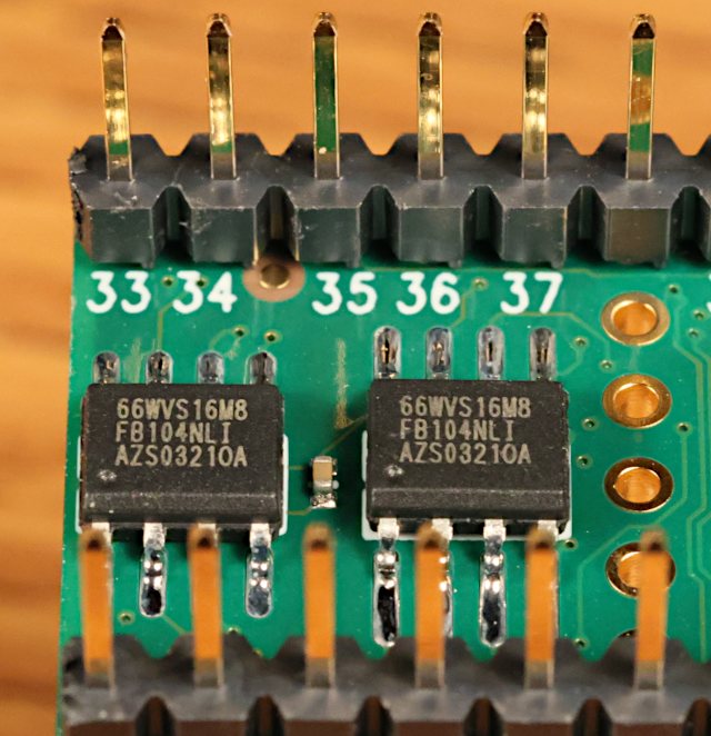
16MB PSRAM Chip
The new 16MB PSRAM chip available from ProtoSupplies (full part number IS66WVS16M8FBLL-104NLI) is now officially supported. Previously only an 8MB chip was supported.
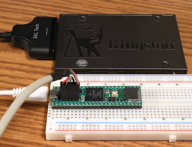
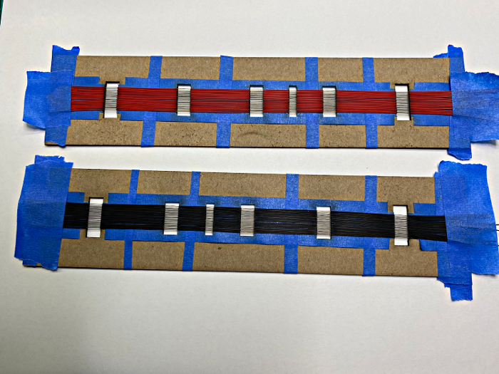
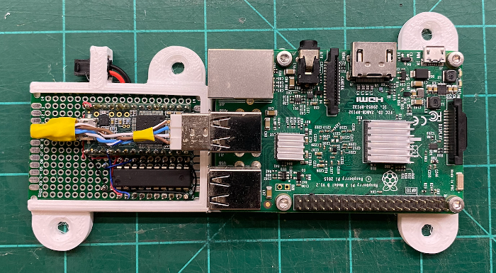
You can solder 1 or 2 of these 16MB chips to the bottom side of Teensy 4.1 to expand its memory. ProtoSupplies also sells Teensy 4.1 with these chips soldered.
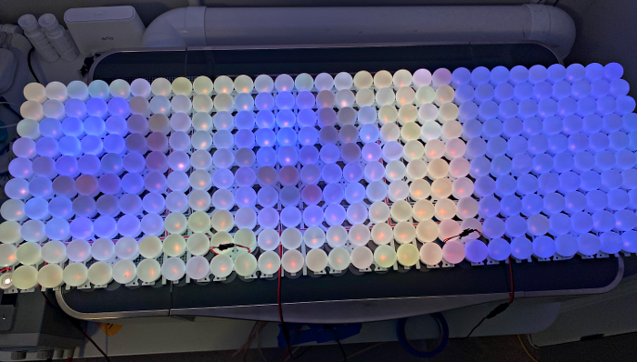
Larger PSRAM memory is particularly useful for polyphonic sample-based musical synthesis (demo video) and fast data logging applications which need a large buffer to deal with ongoing data collection while experiencing SD card or network latency.
The default clock speed for external memory is also increased by 1.60, so either 8MB or 16MB chips will perform faster than with prior versions.
Jonathan Oakley deserves credit for much of the work to support this new chip.
Lockable Teensy in Arduino IDE 2
Using Lockable Teensy involves running 3 programs to initialize the hardware with your encryption key. Once initialized, it can be used as normal where all programming is done with encrypted .ehex rather than a normal .hex file.
Generating the initialization programs previously required using Arduino 1.8.19, or command line utilities, because Arduino 2.x.x doesn’t support the Java-based plugins from older Arduino IDE.
Version 1.60 brings this plugin to Arduino IDE 2.x.x using the Typescript plugin system.
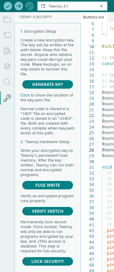
One unfortunate side effect is an empty “Teensy 4 Security” menu appears. This is a bug Arduino IDE 2 inherits from Theia IDE. It has been assigned Arduino IDE issue #2848. Hopefully future Arduino IDE will fix this issue.
Wire Slave Mode on Teensy 4
Wire slave mode, where Teensy acts as a I2C peripheral, has been improved.
A common I2C usage is a write transaction followed by a read transaction which uses repeated start, so the entire write-then-read operation is a single usage of the I2C bus. Previously the onReceive() and onRequest() functions would be called in the wrong order. 1.60 fixes handling of repeated start, so onReceive() is called first, which allows your program to make use of the info received when onRequest() is called.
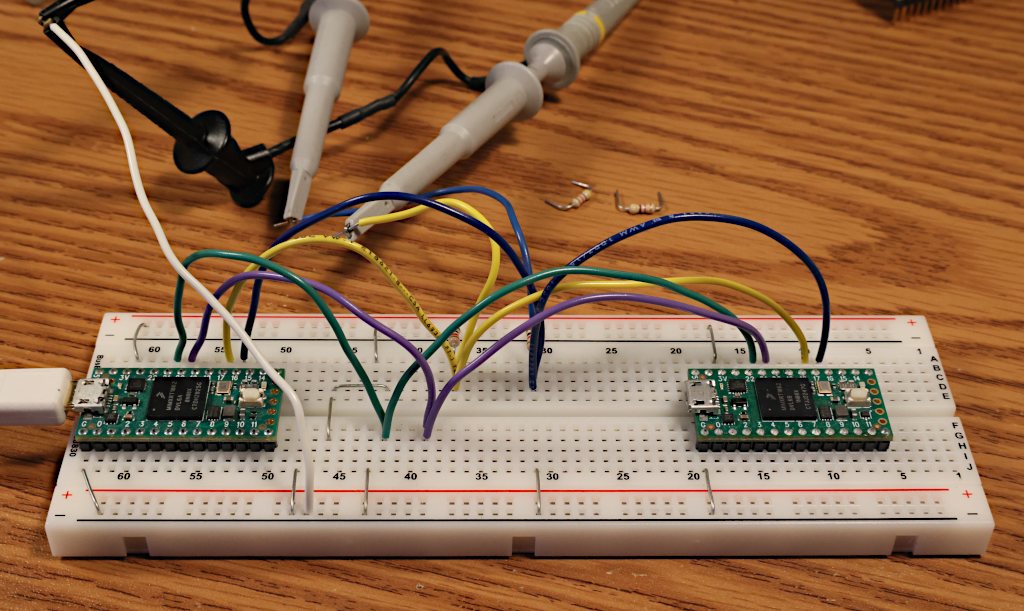
Slave mode now uses a glitch filter which prevents noise coupled to the SDA and SCL lines from disrupting communication. This problem was discovered by an application transmitting digital audio data and I2C control between boards, where the audio clock signal could interfere.
Use of Teensy 4.x in as an I2C slave device should be more reliable with version 1.60.
SoftwareSerial on Teensy 4 and Teensy 3
SoftwareSerial is finally fully supported on all Teensy boards.
For new projects on Teensy 4, you can achieve many more serial ports with FlexIO_t4 FlexSerial which creates more ports with hardware-based FlexIO. SoftwareSerial support is mainly meant for compatibility with Arduino sketches written for Arduino Uno.
Previously on Teensy 3 and Teensy 4, SoftwareSerial was just a thin abstraction which used real hardware serial ports. It only worked if you chose the pins of an actual serial port. This allowed programs written for Arduino Uno to work with only minor edit and choosing different pins. Now those program can work “out of the box”.
The new implementation on Teensy 3 and Teensy 4 uses pin and timer interrupts to receive, so it doesn’t block the CPU for other interrupts like SoftwareSerial on most other boards. 10 interrupts per received byte is less efficient than only 1 with FlexSerial or less with regular serial which uses a hardware FIFO, but a huge improvement compared to blocking all interrupts for the duration of the incoming byte.
USB Keyboard NKRO
Teensy USB Keyboard mode can now support all-keys NKRO communication to your PC.
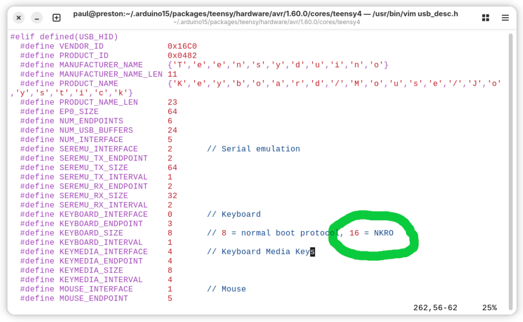
Traditional 6 key mode is still the default, for maximum compatibility with PC bios and KVM switches. To enable NKRO mode, you must edit usb_desc.h within the core library. Simply change KEYBOARD_SIZE to 16 for all-keys NKRO.
NKRO mode uses 1 bit for every key, so any combination of any number of keys may be pressed simultaneously. This can be useful for controlling music synthesis software and video games.
Bug Fixes and Updates
- HardwareSerial XBAR pins 7, 8, 36 on Teensy 4 fixed thanks to KurtE
- HardwareSerial receive with setRX fixed on Teensy 4 thanks to sndsgd
- HardwareSerial serialEvent fixed on Teensy 3
- digitalWriteFast() now check for valid pin number in non-const pin case
- Fix extmem_realloc with NULL on Teensy 4.1
- Fix __SSAT return type
- FS class now has virtual destructor
- Audio fix TDM2 input and output thanks to Jonathan Oakley
- Audio fix stuck AudioEffectFade with no input thanks to Jonathan Oakley
- Audio fix AudioEffectFreeverbStereo thanks to Synvox
- Audio fix AudioSynthToneSweep buffer overflow thanks to Steven Hazel
- Audio improve AudioEffectReverb thanks to Eric Brombaugh
- Audio fix for Teensy LC code thanks to Mark Tillotson
- Teensy Loader waits longer for large flash erase
- Suppress pointless C++ ABI warnings
- Fix erroneous “Teensy should be selected from teensy ports” message
- Audio effect envelope: don’t re-start release if noteOff() called, thanks to Jonathan Oakley
- Audio effect granular: add guard macros, thanks to Jonathan Oakley
- Audio effect reverb: fix reverb cut off when incoming data stops, thanks to Jonathan Oakley
- Improve Teensy Loader toolbar icons on Windows
- Fix Teensy Loader toolbar on MacOS
- SD Improve SDIO media presence detection
- SdFat SPI driver avoid 512 byte stack usage, thanks to KurtE
- LittleFS update Fujitsu FRAM, thanks to mjs513
- SerialFlash fix use of alternate SPI ports, thanks to KurtE
- ST7735_t3 support 320×480, thanks to KurtE
- ST7735_t3 fix colors with setRotation(2), thanks to Jonathan Oakley
- USBHost_t36 KeyboardController delete debug messages, thanks to Tristan Rowley
- Fix DMA TCD copy out of order by compiler optimization, thanks to jmarsh
- FS class and LittleFS use constexpr constructor
- Improve PLL PFD setup, hopefully fixes weird crashes, removes need for startup hacks
- Fix AudioMemory with optimize Smallest Code with LTO
- DMAChannel default channel preemption settings
- SdFat examples recommend at most 25 MHz for SPI
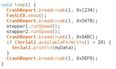
- CrashReport minor changes to printed message, thanks to Shawn Silverman
- USB Keyboard define GUI key names
- USB MIDI receive return channel=0 for system messages
- USBHost_t36: recover from device errors during enumeration
- Libraries updated: ST7735_t3, FlexIO_t4, ILI9488_t3, LittleFS, QuadEncoder, ShiftPWM
Build Process and MacOS Support
The systems used to build Teensy software have been updated. Teensy Loader is now built with wxWidgets 3.2.6, rather than a variety of very old versions different to each operating system.
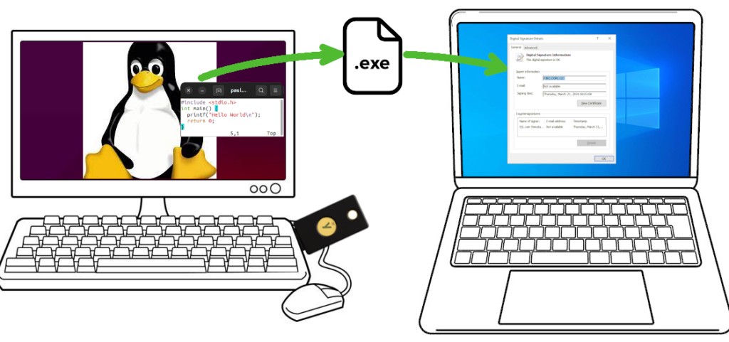
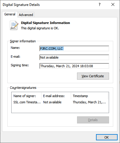
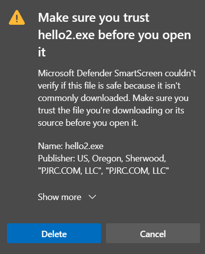
Much of this change was needed because of changes in application signing practices for Windows and MacOS. For Windows, code signing certificates are now issued only by hardware keys. For MacOS, Apple discontinued notarization from older versions of X-code, effectively blocking older Macs.
One unfortunate side effect is we had to discontinue supporting old Arduino IDE 1.8.x on MacOS. Teensyduino still full supports use of Arduino IDE 2.x.x on MacOS.
Support for Linux i686 (32 bit Intel X86) was also dropped.
While these changes drop support for old systems, the updated build process uses newer toolchains which should give better long-term support than the older software used to build all prior Teensy software.