PCM1802 is an impressive audio A/D converter, specified for 105 dB signal to noise (A weighted). But people have reported problems using very cheap PCM1802 breakout boards. Today I made it work.
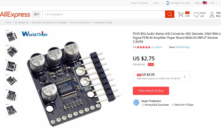
The cheap PCM1802 boards are sold my many Chinese companies, usually for just a few dollars.
Update: since this article was written, new PCM1802 breakout boards have appeared on the market which may have another design problem with the configuration pins. PJRC has not yet tested any new PCM1802 with this issue.
The PCM1802 tested in this article came from this AliExpress vendor.
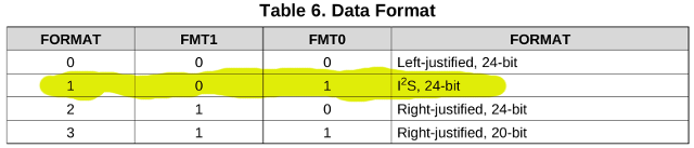
The main issue with these PCM1802 boards involves configuring the data format. Teensy and most microcontrollers use I2S format. The board comes with no documentation, but the PCM1802 datasheet shows how to configure the chip in table 6.
On the bottom side of the PCM1802 breakout are little solder pads with names that match up with the datasheet.
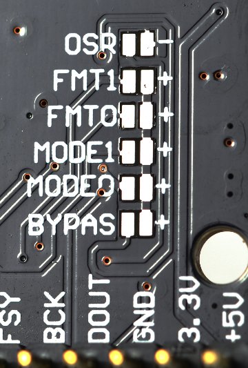
If you power the board, the FMT0 and FMT1 pads measure 0 volts. Without power, the also measure about 9K ohms to GND.
To configure for I2S, you would expect to just solder the 2 pads next to FTM0 together. But there is a problem…
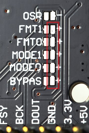
These 5 pads labeled “+” connect to each other, but they do NOT connect to 3.3V or anything else on the circuit board! Soldering the FTM0 pads together has no effect.
To make this work, I soldered a wire to those pads.
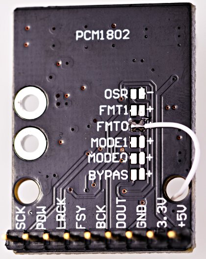
There is no location on the bottom of the board to access 3.3V power. I considered using the OSR pad. But the pullup resistor is only 10K. The PCM1802 has 50K pulldown resistors, according to the datasheet. Indeed with power applied, I measured 2.8 volts at the OSR pad.
So to get 3.3V, I ran the wire to the top side and soldered it to the 3.3V pin.
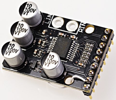
The SOT23 part in the lower left corner of this photo is a 3.3V regulator. This 3.3V pin is an output, not an input, which I also verified with my voltmeter.
Fortunately, all of the other pins in this PCM1802 board are wired correctly for use with Teensy’s I2S. In its default mode, only DOUT is an output. All of the other signals are inputs.
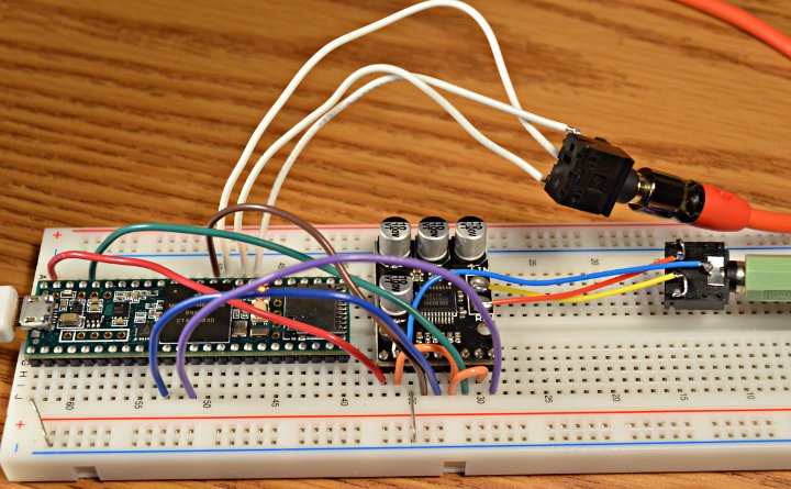
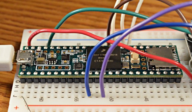
These are the required connections between Teensy 3.6 and the PCM1802 breakout board.
PCM1802 Teensy 3.6
   +5V               VIN
   3.3V
   GND              GND
   DOUT            DIN (13)
   BCK               BCLK (9)
   FSY               3.3V
   LRCK             LRCLK (23)
   POW              3.3V
   SCK               MCLK (11)
The POW pin is the only name which doesn’t match up with the PCM1802 datasheet. I used my ohmmeter to verify it really is connected to the PDWM pin.
The FSY pin (connected to FSYNC) is also a bit unusual. PCM1802 expects it to be logic high while you transmit data, so just connect to 3.3V. In the other modes, it sends a signal on this pin which is high during data bits and low during the zero padding bits. But it does not require that signal as input. FSYNC just connects to 3.3V to use PCM1802 with Teensy.
For a simple test, I programmed Teensy 3.6 with minimal code to just route the I2S input data to the two DAC pins.
#include <Audio.h>

AudioInputI2S i2s1; //xy=152,100
AudioOutputAnalogStereo dacs1; //xy=316,117
AudioConnection patchCord1(i2s1, 0, dacs1, 0);
AudioConnection patchCord2(i2s1, 1, dacs1, 1);

void setup() {
 AudioMemory(10);
}

void loop() {
}
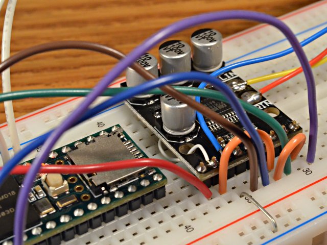
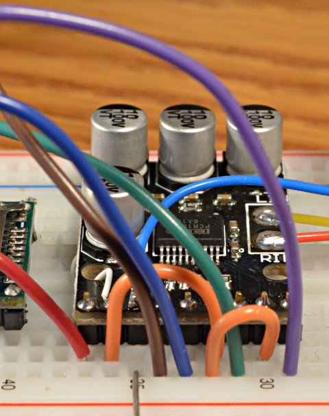
With FMT0 correctly configured using a mod wire, and those connections, PCM1802 works great with Teensy. Here are closer photos of the wiring.
If you need a high quality audio A/D and you can find these cheap PCM1802 breakout boards, hopefully this tip about the FTM0 hack and known-good wiring can save you from some frustration and get your project up and running quickly.