Some time ago, I needed to actually “see” a current waveform in the 100 uA to 5 mA range with at least a couple MHz bandwidth. This extremely expensive probe would have been perfect, but instead I built something similar for about $30 using the amazing Analog Devices AD8428 amplifier.
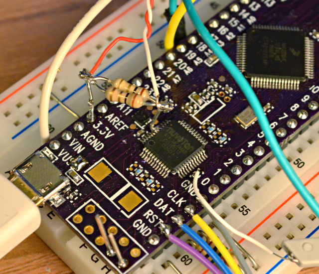
The first step was cutting the power trace and adding a resistor. I used two 1 ohm resistors in parallel.
At 5 mA, this makes only 2.5 mV. My scope’s supposed resolution is 1 mV, but the truth is there’s plenty of noise down in the 1 mV range. That’s pretty common for most scopes, even pretty spendy ones. So it’s just not feasible to measure this signal directly (not to mention using 2 probes and subtracting them in the scope).
That incredibly expensive Agilent probe probably has a couple really nice amplifiers inside…. so I went searching for an amplifier. After a bit of searching, I found the AD8428. It has a fixed gain of 2000 and a bandwidth of 3.5 MHz. That’s a gain-bandwidth product of 7 GHz !!! It’s also an extremely well matched instrumentation amp with an amazing CMRR of 140 dB. So it gets rid of the power supply voltage and outputs the amplified signal referenced to ground.
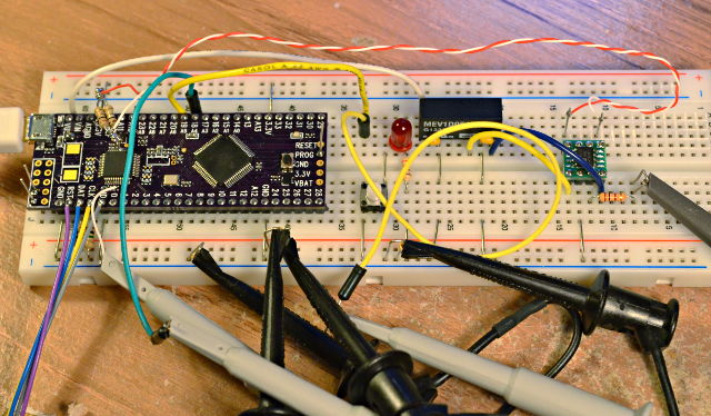
The AD8428 is perfect. It’s so very easy! Of course, such amazing performance costs money: about $20. Here’s that expensive little amplifier, and a 5V to +/- 15V power supply (about $10) to power it.
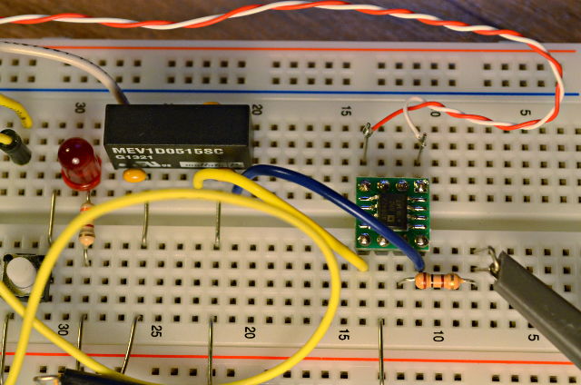
The one trick with measuring such tiny voltages is twisting the 2 sense wires together. Honestly, I didn’t try it running them separately, but since this thing is getting voltages in only the microvoltage range for the lower measurements, I didn’t want to risk picking up noise. I also put a 100 ohm resistor on the output, just in case I accidentally short the output or do something clumsy that might blow that little $20 part.
Here’s a scope screenshot using this little amplifier to “see” the current (the blue waveform).
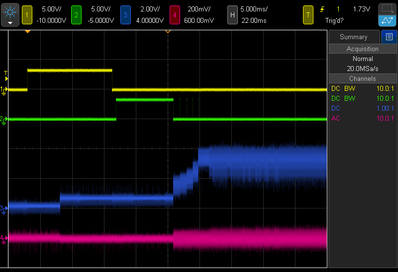
In this test, the microcontroller is running in its slowest mode at only 10 kHz, drawing about 120 uA. Then when the chip’s internal oscillator is started, the current jumps to about 600 uA. Later, the CPU switches to actually clocking from that oscillator. There’s an on-chip clock divider which is switched in and increased gradually.
The bottom trace (red) is the voltage on the chip’s 1.8V linear regulator. It turns out that sudden jumps in current cause pretty substantial downward spikes on the regulated voltage. This more gradual startup approach really helps. This sort of thing is impossible to see with a slow multimeter, but with a reasonably good bandwidth measurement of the current, it’s easy to see what various code actually does to the current.
I tried connecting my multimeter to the amp output. Sometimes it’s just a lot more convenient to look at a single number on a meter than fiddle with the scope. I had been using the current mode on the meter before building this. One thing I was surprised to find it my little meter updates its screen much faster while measuring about 125 mA than it does when measuring 125 uA.
Another interesting thing I’ve been noticing is patterns within the blue current waveform. This Agilent scope has a “digital phosphor” rendering of the huge amount of data it collected. This static screenshot can’t really capture the interactive experience of adjusting the waveform intensity, where various regions within the data change brightness differently, indicating there’s something interesting/different going on. Even so, you can see several areas in the screenshot where interesting things are happening once the CPU is up and running. It’s interesting how the current waveform changes as different code executes.
I know this isn’t anything terribly impressive… basically just buy a high-end amplifier and use it with a series resistor. Maybe it even reads like an Analog Devices ad? I’m not affiliated with Analog Devices… I just bought this part at normal qty 1 pricing from Digikey.
Still, this is the first time I’ve ever really looked at such low microcontroller currents with a few MHz bandwidth, and I’m guessing not many people have ever bothered to really measure such currents, so I thought I’d share.
Years ago I originally posted this article to the DorkbotPDX site. Hackday published an article about it at the time. Since then, the DorkbotPDX blog section has vanished. I’m reposting it here, to preserve the info… for the next time I or others might need to do this sort of current measurement on a budget.