During the Teensy 4.0 beta test we made these breakout boards, to easily test hardware features. They were also sent to Hackaday, Hackster, and Hackspace Magazine for reviews.
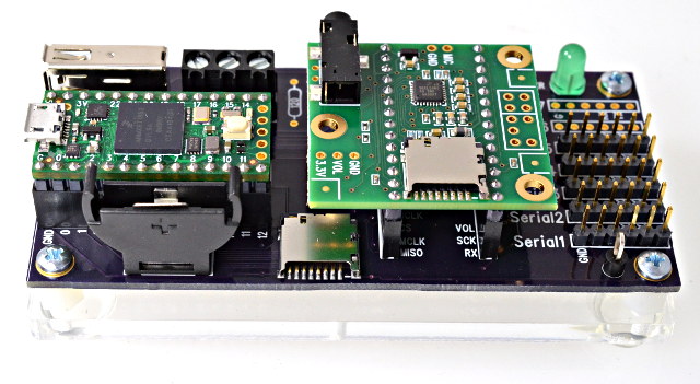
Now we’re sharing all the info, so you can make your own copy of this breakout board!
Breakout Board Features
First, let’s look at the main features.
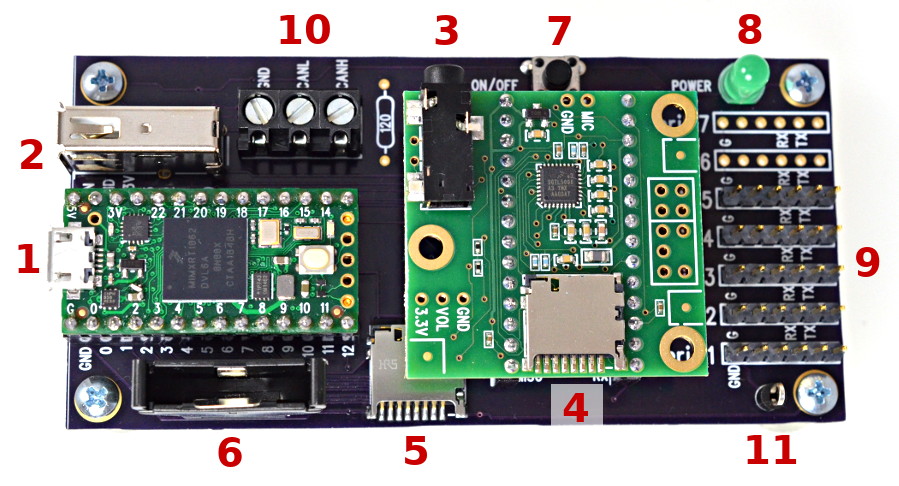
- Main USB for Teensy 4.0. The entire board gets power from this USB connector, so it must be plugged in for the eval board to work.
- Second USB host port. To test this, plug in a USB keyboard or MIDI keyboard or drum pad. In Arduino, click File > Examples > USBHost_t36 > Test for a simple program which responds to events from those types of USB devices. The eval board has a TPS2055A current limit chip, which allows most USB devices to be hot plugged while running from USB power provided over the main USB port.
- Audio shield output. Plug in headphones or computer speakers. Recommend running File > Examples > Audio > Synthesis > Guitar to test the audio output.
- SD card accessed by SPI with pin 10 for CS. The eval kit comes with a 32 GB card pre-loaded with 4 public domain music files. Recommend running File > Examples > Audio > WavFilePlayer for a first test.
- SD card accessed by SDIO (4 bit). To test this, run any of the SD library examples. Edit the chip select pin to BUILTIN_SDCARD. An 8 pin flat flex cable connects between the Teensy 4.0 and peripheral board to provide access to the SDIO pins.
- Coin cell holder (CR2032 type battery), for RTC backup. Run File > Examples > Time > TimeTeensy3 to access the RTC date/time.
- Power On/Off button. Hold for 5 seconds to completely shut off 3.3V power. Press for 1/2 second to turn back on. If a coin cell is installed, the power on/off state will be retained when you disconnect the USB cable. Without the coin cell to maintain power management state, the 3.3V power will default to “on” when power is applied.
- Power LED, to visually confirm if the 3.3V power is turned on.
- Serial1 to Serial7. These 6 pin headers mate with the commonly available FTDI TTL-level cables, and numerous boards following that 6 pin format. For a quick test program, click File > Examples > Teensy > Serial > EchoBoth. If using Serial2 or higher, edit the define in that program.
- CAN FD port. Use the FlexCAN_t4 library to access this port. Unfortunately, the labels printed on the eval board are backwards. On the original boards (shown in these photos), the center pin labeled “CANL” is actually “CANH”, and the right hand pin labeled “CANH” is actually “CANL”. The shared PCB files have this error corrected. If your CAN bus requires a termination, a 120 ohm resistor can be soldered to the eval board.
- Ground test point. Handy if you wish to make measurements with a voltmeter or oscilloscope. 🙂
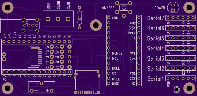
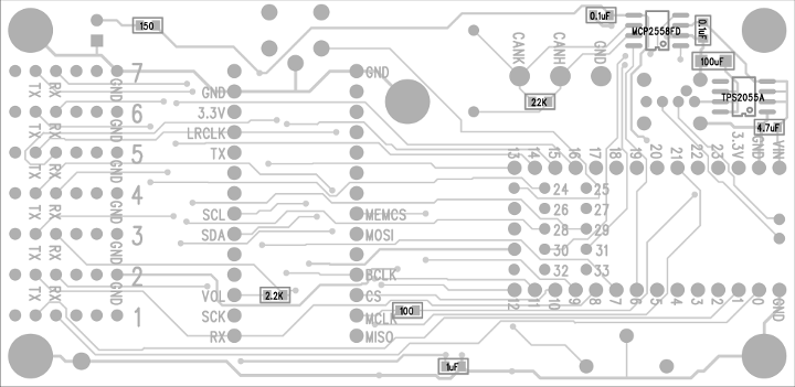
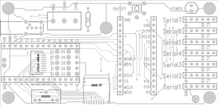
Circuit Board
The PCB is available as an OSH Park shared board. You can buy it from OSH Park, or use the Download button on that page to get the PCB gerber files.
Connections to Teensy 4.0 Bottom Side
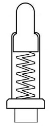
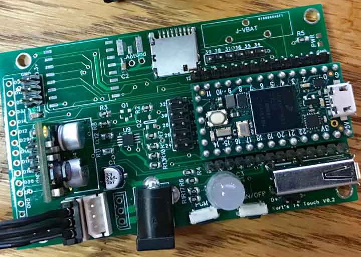
To connect to the bottom side of Teensy 4.0, the breakout board uses these spring-loaded pogo pins. Either 12 to 12.5 mm height can be used for the pins which touch the flat surface mount pads. 12.5 works best to contact to the On/Off and VBAT pins.
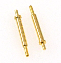
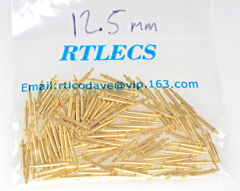
These pogo pins were purchased from RTLECS. (new RTLECS link) RTLECS sells on Aliexpress, Ebay and maybe other sites. If you have trouble finding them, the ones we used for the beta test came in this bag with contact info.
While there are 14 locations to solder these these pogo pins, Teensy pins 26, 27, 32, 33 are not routed on the breakout board. You only need 10 pogo pins to fully utilize all the breakout board features. Many of the ones built for the beta test had only 6 pogo pins, leaving off the 4 pins to for Serial6 & Serial7.
The 8 pins for native SD card support are connected by a FFC (flat flex cable) between Teensy 4.0 and the breakout board.
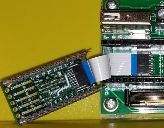
Credit to Defragster for sharing this photo on the forum. Also in this photo you can see one of the earlier beta test boards, which had a white wire soldered to the bottom to correct a brown-out restart problem discovered during beta testing. The final Teensy 4.0 boards have this wire routed on layer 3 (of 6) inside the PCB.
Parts List
Here is a complete list of parts needed to fully build the breakout board. Some of these parts may be left off if you do not need all the breakout board features.
 1 Teensy 4.0
 1 Audio Shield, Rev B or Rev C
 1 Resistor, 100 ohm, 805
 1 Resistor, 150 ohm, 805
 1 Resistor, 2.2K ohm, 805
 1 Resistor, 22K ohm, 805
 2 Capacitor, 0.1 uF, 805
 1 Capacitor, 1.0 uF, 805
 1 Capacitor, 4.7 uF, 805
 1 Capacitor, 100 uF, 1206
 1 MCP2558FD CAN-FD Transceiver, Digikey MCP2558FD-H/SN-ND
 1 TPS2055A USB Current Limit Switch, Digikey 296-3418-5-ND
 2 Connector, FFC 8 pin, HFW8R-1STE1H1LF or HFW8R-1STE1LF
 1 Connector, Micro SD, DM3D-SF, Digikey HR1941TR-ND
 1 Battery Holder, CR2032 (commonly sold on Ebay & Aliexpress)
 4 Socket, 14 pin
 7 Header, 6 pins
 1 Connector, Terminal Block, 3 pin, 5.08mm
 1 Connector, USB Host, Digikey 609-1041-ND (good) or ED2991-ND (cheap)
 1 LED, Green, T1-3/4, Digikey 1080-1128-ND
 1 Connector, Test Point, Digikey 36-5011-ND
10 Pogo Pin, 12 mm, RTLECS PGTH1250
 1 Pushbutton, 5 pin
 1 FFC Cable, 8 pin, same side contacts, Digikey AE11351-ND
 4 Header, 14 pin
 1 Acrylic Base, 1/4, laser cut
 5 Standoff, Hex M-F, 4-40, 1/4, Digikey 36-4800-ND
 5 Machine Screw, 4-40, 3/16
Assembly Steps
To build the breakout board, first solder the bottom side parts.
When building the top side, first solder the FFC connector and SD socket, if you wish the use the native SD card.
Before soldering any other through-hole parts, solder the pogo pins. Getting these 12.5 mm tall pins aligned at a right angle to the PCB is tricky. The beta boards were held in a Stick Vise to keep the board flat with the table facing top side up and the surface covered with extra liquid flux, then the pins inserted and heated from their side while a small amount of solder was applied. They take quite some time to cool down. Use caution to avoid burned fingers!
After soldering the pogo pins, the rest of the through-hole parts can be soldered in any order. The 14 pins sockets make a nice a temporary alignment tool to hold the 6 pin headers straight. Placing your Teensy into the 14 pin sockets during soldering guarantees they are aligned so it will later fit properly.
Acrylic Base
The final (optional) piece is this laser cut acrylic base.

The file used for these as SVG (zip download) can be used to get a proper fit. After laser cutting, the 5 holes were threaded with a #4-40 tap.
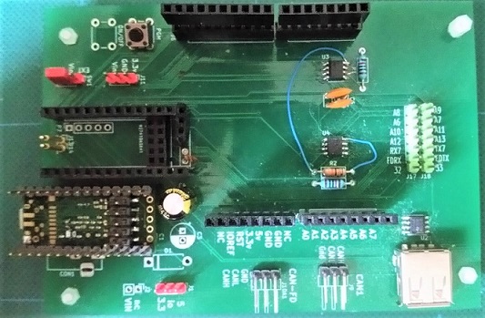
Kurt’s Breakout Board
Kurt shared on the forum this breakout board, plus another he is developing. His boards have many features not found on the PJRC beta test breakout board.
Kurt publishes his designs on github, as Diptrace files and gerber files you can send to any PCB fabrication company.
Mike’s Breakout Board
Mike also shared his breakout board on the forum.
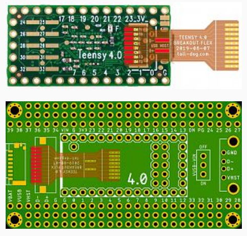
Tall Dog’s Upcoming Breakout Board
Tall Dog is working on a breakout board for Teensy 4.0, which you will be able to buy as a kit. They shared this preliminary image on the forum. This is still in the planning stage, so the final product may look different.
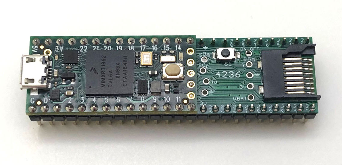
FRDM4236 Board
Felix (aka Trainer2Edu) created this add-on board which solders to the bottom side of Teensy 4.0