Embrace Heart Sequenced Incandescent Light Dimming

I worked on a tiny piece of the Embrace sculpture at Burning Man 2014.

Inside were 2 hearts, one made here in Portland by Lostmachine Andy & others at Flat Rat Studios.  I made electronics to gradually fade 4 incandescent light bulbs in heart beating patterns.

These wonderful photos where taken by Sarah Taylor.

Inside the enormous sculpture were two hearts.  The blue on was built by a group in Vancouver, B.C., Canada, and of course this one was built here in Portland, Oregon, USA.

Andy wanted this heart to have a very warm, gentle atmosphere, with warn incandescent bulbs slowly fading to create the heart beat.  These effect turned out quite well.  Andy really knows his stuff!

Here’s a great time-lapse video where you can see the slow, gradual incandescent light fading as a rapid heart beat.  Skip forward to about 0:36 in this video.


The light fading was done using a Teensy-based 4-channel AC dimmer board, on this 4 by 3.5 inch circuit board.

Here’s a quick video, from the first test of the light controller.

Four BT139X Triacs that actually switch the AC voltage are mounted on the bottom side to a heatsink that’s meant to dissipate any heat to the metal case.  Originally Andy believed the lights might be 500 watts each, so I was concerned about heat.  In the end, four 60 watt bulbs were used and the Triacs did not get noticeably warm.

Here is a parts placement diagram for building the circuit board.  Two boards were built, the one that ran the project and a spare… just in case!

The PCB cad files are attached below, if anyone wants to make more of these boards.

The AC switching circuitry was basically Fairchild Semiconductor’s recommended circuit for the MOC3023 optical isolator, which allows a Teensy 2.0 board to safely control the AC voltage.  Four copies of this circuit were built on the board.

This circuit requires the Teensy 2.0 to know the AC voltage timing, so it can trigger the Triac at the right moment.  Triggering early in the AC waveform causes the Triac to conduct near the full AC voltage for maximum brightness.  Triggering later reduces the brightness.

To get the AC timing, I built this special power supply onto the board.

The Teensy 2.0 receives pulses on pins 5 and 6 as the AC waveform cycles positive and negative.

One caveat is this approach depends on the AC voltage being a sine wave.  The AC voltage was one of the first questions I asked Andy, and he was told Burning Man would supply a true sine wave AC voltage.  When he got out there, it turned out the power was actually a “modified sine wave”, which really isn’t anything like a sine wave.  This circuit didn’t work well.  Fortunately, they were able to run the lighting from a small generator that produced a true sine wave.

With the AC timing arriving on pins 5 and 6, and 4 pins able to trigger Triacs, and 3 pins connected to analog voltages for changing speed, brightness and pattern, the only other major piece of this technology puzzle is the software.

In this code, loop() tracks the changes in the waveform on pins 5 & 6, and it fires the Triacs at their programmed times.  120 times per second (each AC half cycle), the recompute_levels() function runs, which reads the analog controls and changes the Triac time targets, which loop() uses to actually control the voltage outputs.

Here’s all the code:

void setup()
{
	pinMode(0, INPUT_PULLUP);	// unused
	pinMode(1, INPUT_PULLUP);	// unused
	pinMode(2, INPUT_PULLUP);	// unused
	pinMode(3, INPUT_PULLUP);	// unused
	pinMode(4, INPUT_PULLUP);	// unused
	pinMode(5, INPUT);		// Phase A
	pinMode(6, INPUT);		// Phase B
	pinMode(7, INPUT_PULLUP);	// unused
	pinMode(8, INPUT_PULLUP);	// unused
	pinMode(9, INPUT_PULLUP);	// unused
	pinMode(10, INPUT_PULLUP);	// unused
	digitalWrite(11, LOW);
	pinMode(11, OUTPUT);		// LED
	digitalWrite(12, HIGH);
	pinMode(12, OUTPUT);		// trigger4, low=trigger
	digitalWrite(13, HIGH);
	pinMode(13, OUTPUT);		// trigger3, low=trigger
	digitalWrite(14, HIGH);
	pinMode(14, OUTPUT);		// trigger2, low=trigger
	digitalWrite(15, HIGH);
	pinMode(15, OUTPUT);		// trigger1, low=trigger
	pinMode(16, INPUT_PULLUP);	// unused
	pinMode(17, INPUT_PULLUP);	// unused
	pinMode(18, INPUT_PULLUP);	// unused
	analogRead(19);			// pot #3
	analogRead(20);			// pot #2
	analogRead(21);			// pot #1
	pinMode(22, INPUT_PULLUP);	// unused
	pinMode(23, INPUT_PULLUP);	// unused
	pinMode(24, INPUT_PULLUP);	// unused
}


uint8_t pot1=0, pot2=0, pot3=0;
uint8_t level1=100, level2=128, level3=0, level4=250;


uint8_t phase_to_level(uint16_t phase)
{
	uint16_t amplitude;

	// 10923 = 32768 / 3
	//     0 to 10922 = increasing: 0 -> 32767
	// 10923 to 21845 = decreasing: 32767 -> 0
	// 21846 to 32768 = increasing: 0 -> 32767
	// 32769 to 43691 = decreasing: 32767 -> 0
	// 43692 to 65535 = resting: 0

	if (phase < 10923) {
		amplitude = phase * 3;
	} else if (phase < 21845) {
		phase = phase - 10923;
		phase = 10922 - phase;
		amplitude = phase * 3;
	} else if (phase < 32768) {
		phase = phase - 21846;
		amplitude = phase * 3;
	} else if (phase < 43691) {
		phase = phase - 32769;
		phase = 10922 - phase;
		amplitude = phase * 3;
	} else {
		amplitude = 0;
	}
	//amplitude = (phase < 32768) ? phase : 65535 - phase;
	amplitude >>= 6;  // range 0 to 511
	amplitude *= (pot2 + 84) / 6;  //
	amplitude += 6000 + pot2 * 8; // minimum brightness
	return (amplitude < 32768) ? amplitude >> 7 : 255;
}

void recompute_levels()
{
	static uint16_t phase=0;
	static uint8_t n=0;

	analog_update();
	//Serial.print("pot: ");
	//Serial.print(pot1);
	//Serial.print(", ");
	//Serial.print(pot2);
	//Serial.print(", ");
	//Serial.print(pot3);
	phase += (((uint16_t)pot1 * 83) >> 5) + 170;
	//Serial.print(", phase: ");
	//Serial.print(phase);
	if (pot3 < 128) {
		level1 = phase_to_level(phase);
		level2 = level1;
		level3 = phase_to_level(phase + pot3 * 52);
		level4 = level3;
	} else {
		uint16_t n = (pot3 - 127) * 26;
		level1 = phase_to_level(phase);
		level2 = phase_to_level(phase + 6604 - n);
		level3 = phase_to_level(phase + 6604);
		level4 = phase_to_level(phase + 6604 + n);
	}
	//Serial.print(", levels: ");
	//Serial.print(level1);
	//Serial.print(", ");
	//Serial.print(level2);
	//Serial.print(", ");
	//Serial.print(level3);
	//Serial.print(", ");
	//Serial.print(level4);
	//Serial.println();
}


void loop()
{
	uint8_t a, b, prev_a=0, prev_b=0, state=255, triggered=0;
	uint32_t usec, abegin, bbegin, alen, blen;
	uint16_t atrig1, atrig2, atrig3, atrig4;
	uint16_t btrig1, btrig2, btrig3, btrig4;
	bool any;

	while (1) {
		// read the phase voltage and keep track of AC waveform timing
		a = digitalRead(5);
		b = digitalRead(6);
		if (a && !prev_a) {
			// begin phase A
			usec = micros();
			if (state == 0) {
				state = 1;
				abegin = usec;
				triggered = 0;
				Serial.print("A");
				Serial.println(usec);
			} else if (state == 255) {
				state = 11;
				abegin = usec;
			} else {
				state = 255;
			}
		}
		if (!a && prev_a) {
			// end phase A
			usec = micros();
			if (state == 1) {
				state = 2;
				alen = usec - abegin;
				Serial.print("a");
				Serial.print(usec);
				Serial.print(",");
				Serial.println(alen);
				if (alen < 12000) {
					// compute trigger offsets for next A phase
					recompute_levels();
					atrig1 = level1 ? ((256 - level1) * alen) >> 8 : 30000;
					atrig2 = level2 ? ((256 - level2) * alen) >> 8 : 30000;
					atrig3 = level3 ? ((256 - level3) * alen) >> 8 : 30000;
					atrig4 = level4 ? ((256 - level4) * alen) >> 8 : 30000;
				} else {
					state = 255;
				}
			} else if (state == 11) {
				state = 12;
				alen = usec - abegin;
			} else {
				state = 255;
			}
		}
		if (b && !prev_b) {
			// begin phase B
			usec = micros();
			if (state == 2) {
				state = 3;
				bbegin = usec;
				triggered = 0;
				Serial.print("B");
				Serial.println(usec);
			} else if (state == 12) {
				state = 13;
				bbegin = usec;
			} else {
				state = 255;
			}
		}
		if (!b && prev_b) {
			// end phase B
			usec = micros();
			if (state == 3) {
				state = 0;
				blen = usec - bbegin;
				Serial.print("b");
				Serial.print(usec);
				Serial.print(",");
				Serial.println(blen);
				if (blen < 12000) {
					// compute trigger offsets for next B phase
					recompute_levels();
					btrig1 = level1 ? ((256 - level1) * blen) >> 8 : 30000;
					btrig2 = level2 ? ((256 - level2) * blen) >> 8 : 30000;
					btrig3 = level3 ? ((256 - level3) * blen) >> 8 : 30000;
					btrig4 = level4 ? ((256 - level4) * blen) >> 8 : 30000;
				} else {
					state = 255;
				}
			} else if (state == 13) {
				state = 0;
				blen = usec - bbegin;
			} else {
				state = 255;
			}
		}
		prev_a = a;
		prev_b = b;

		// trigger triacs at the right moments
		if (state == 1) {
			usec = micros();
			any = false;
			if (!(triggered & 1) && usec - abegin >= atrig1) {
				digitalWrite(15, LOW);
				triggered |= 1;
				any = true;
				//Serial.println("trig1(a)");
			}
			if (!(triggered & 2) && usec - abegin >= atrig2) {
				digitalWrite(14, LOW);
				triggered |= 2;
				any = true;
				//Serial.println("trig2(a)");
			}
			if (!(triggered & 4) && usec - abegin >= atrig3) {
				digitalWrite(13, LOW);
				triggered |= 4;
				any = true;
				//Serial.println("trig3(a)");
			}
			if (!(triggered & 8) && usec - abegin >= atrig4) {
				digitalWrite(12, LOW);
				triggered |= 8;
				any = true;
				//Serial.println("trig4(a)");
			}
			if (any) {
				delayMicroseconds(25);
				digitalWrite(15, HIGH);
				digitalWrite(14, HIGH);
				digitalWrite(13, HIGH);
				digitalWrite(12, HIGH);
			}
		} else if (state == 3) {
			usec = micros();
			any = false;
			if (!(triggered & 1) && usec - bbegin >= btrig1) {
				digitalWrite(15, LOW);
				triggered |= 1;
				any = true;
				//Serial.println("trig1(b)");
			}
			if (!(triggered & 2) && usec - bbegin >= btrig2) {
				digitalWrite(14, LOW);
				triggered |= 2;
				any = true;
				//Serial.println("trig2(b)");
			}
			if (!(triggered & 4) && usec - bbegin >= btrig3) {
				digitalWrite(13, LOW);
				triggered |= 4;
				any = true;
				//Serial.println("trig3(b)");
			}
			if (!(triggered & 8) && usec - bbegin >= btrig4) {
				digitalWrite(12, LOW);
				triggered |= 8;
				any = true;
				//Serial.println("trig4(b)");
			}
			if (any) {
				delayMicroseconds(25);
				digitalWrite(15, HIGH);
				digitalWrite(14, HIGH);
				digitalWrite(13, HIGH);
				digitalWrite(12, HIGH);
			}
		}
	}
}


#define ADMUX_POT1  0x60
#define ADMUX_POT2  0x61
#define ADMUX_POT3  0x64
void analog_update()
{
	static uint8_t count=0;

	switch (count) {
	  case 0: // start conversion on pot #1
		ADMUX = ADMUX_POT1;
		ADCSRA |= (1<<ADSC);
		count = 1;
		return;
	  case 1: // read conversion on pot #1
		if (ADCSRA & (1<<ADSC)) return;
		pot1 = ADCH;
		ADMUX = ADMUX_POT2;
		count = 2;
		return;

	  case 2: // start conversion on pot #2
		ADMUX = ADMUX_POT2;
		ADCSRA |= (1<<ADSC);
		count = 3;
		return;
	  case 3: // read conversion on pot #2
		if (ADCSRA & (1<<ADSC)) return;
		pot2 = ADCH;
		ADMUX = ADMUX_POT3;
		count = 4;
		return;

	  case 4: // start conversion on pot #3
		ADMUX = ADMUX_POT3;
		ADCSRA |= (1<<ADSC);
		count = 5;
		return;
	  case 5: // read conversion on pot #3
		if (ADCSRA & (1<<ADSC)) return;
		pot3 = ADCH;
		ADMUX = ADMUX_POT1;
		count = 0;
		return;
	  default:
		count = 0;
	}
}


This article was originally published on the DorkbotPDX website, on September 3, 2014.  In late 2018, DorkbotPDX removed its blog section.  An archive of the original article is still available on the Internet Archive.  I am republishing this article here, in the hope it may continue to be found and used by anyone interested in the Embrace art installation or any other project needing sequenced AC light dimming effects.


These comments where written on the old site:


From Brandon:

Once we determined that the AC source was modified sine, I knew there wasn’t anything I could do to help the situation easily in the middle of the desert 🙂
As someone who looked over the board and what not, nice job! Worked really well and looked amazing in operation (on the right power source).

Rev two, perhaps rectified DC drive of the incandescent lights to avoid the modified sine issue? So many folks use those types of inverters to cut costs on big artwork solar installations.

Cheers and thanks for contributing!


From Anonymous:

The embrace structure was prettty cool, I got a chance to explore it at Burninman this year. Wish I got to see it burn down, the videos looked amazing. I assume you guys removed the heart materials before that happened.


Better SPI Bus Design in 3 Steps

Most Arduino SPI tutorials show this simple but poor SPI bus design:

Better SPI bus design can prevent conflicts.  3 simple improvements are needed:

  1. Use pullup resistors on all chip select signals.

  2. Verify tri-state behavior on MISO: use a tri-state buffer chip if necessary.

  3. Protect bus access with SPI.beginTransaction(settings) and SPI.endTransaction().

Step 1: Pullup Resistors for Chip Select & Reset Signals

When multiple SPI devices are used, and especially when each is supported by its own library, pullup resistors are needed on the chip select pins.

Without a pullup resistor, the second device can “hear” and respond to the communication taking place on the first device, if that second device’s chip select pin is not pulled up.  This is easy to understand in hindsight, but it can be temendously confusing and frustrating to novice Arduino users who purchase shields or breakout boards without pullup resistors.  Each SPI device works when used alone, but they sometimes mysteriously fail when used together, only because both devices are hearing communication meant to initialize only the first device!

A simpe workaround for devices without pullup resistor involves adding code at the beginning of setup.

    void setup() {
      pinMode(4, OUTPUT);
      digitalWrite(4, HIGH);
      pinMode(10, OUTPUT);
      digitalWrite(10, HIGH);
      delay(1);
      // now it's safe to use SD.begin(4) and Ethernet.begin()
    }

Step 2: Proper MISO Tri-State Behavior

Most SPI chips will tri-state (effectively disconnect) their MISO pin when their chip select signal is high (inactive).

However, some chips do not have proper MISO tri-state behavior.  Fortunately, checking MISO tri-state is easy, especially when prototyping on a breadboard.  Just connect two 10K resistors to the MISO line, like this:

When all SPI chips are disabled, the MISO signal should “float” to approximately half the Vcc voltage.  If any device is still driving the MISO line, you’ll see a logic high (usually close to 3.3V or 5.0V) or logic low (close to zero volts).  This test is so easy, it should always be performed by designers of Arduino compatible products.

Arduino shields and breakout boards with poorly-behaved chips should always include a tri-state buffer.  Adafruit’s CC3000 breakout board is a good example:

Step 3: USB SPI Transactions in Software

Newer versions of Arduino’s SPI library support transactions.  Transactions give you 2 benefits:

  • Your SPI settings are used, even if other devices use different settings
  • Your device gains exclusive use of the SPI bus.  Others will not disturb you.

These improvements solve software conflicts, allowing multiple SPI devices to properly share the SPI bus.

A typical use of transactions looks like this:

    SPI.beginTransaction(SPISettings(14000000, MSBFIRST, SPI_MODE0));
    digitalWrite(chipSelectPin, LOW);
    SPI.transfer(mybyte1);
    SPI.transfer(mybyte2);
    digitalWrite(chipSelectPin, HIGH);
    SPI.endTransaction();

SPI.beginTransaction() takes a special SPISettings variable, which give the maximum clock speed, the data order, and clock polarity mode.  The speed is give as an ordinary number, expressing the maximum clock speed that device can use.  The SPI library will automatically select the fastest clock available which is equal or less than your number.  This allows your code to always use the best speed, even on board with different clock speeds.

If your code will ever call SPI library functions from within an interrupt (eg, from attachInterrupt), you must call SPI.usingInterrupt().  For example:

    SPI.begin();
    SPI.usingInterrupt(digitalPinToInterrupt(mypin));
    attachInterrupt(digitalPinToInterrupt(mypin), myFunction, LOW);

If you are developing a library that must be compatible with older versions of Arduino, which lack these SPI transaction functions, you can use SPI_HAS_TRANSACTION to check for the new version.  For example:

    #ifdef SPI_HAS_TRANSACTION
    SPI.beginTransaction(SPISettings(2000000, LSBFIRST, SPI_MODE1));
    #endif

Please Share and Use This Information

Many SPI-based products for Arduino do not work well together.  My hope is this information can help all makers of Arduino compatible devices to achieve much better compatibility.

Long-term, sharing of knowledge is needed.  Please share this information and ask makers of SPI devices and libraries to consider these suggestions.

This article may be shared and copied under the terms of the Creative Commons Attribution 4.0 International License.  Please, copy & share!  🙂


This article was originally published on the DorkbotPDX website, on November 24, 2014.  In late 2018, DorkbotPDX removed its blog section.  An archive of the original article is still available on the Internet Archive.  I am republishing this article here, in the hope it may continue to be found and used by everyone using SPI chips, and especially companies making SPI-based products for the Arduino community.


Control Voltage to 1.2V Analog Input Pin

Often the question is asked, what is the simplest way to get modular synth control voltage (CV) into an analog input pin?

This simple circuit using only 3 resistors and 1 capacitor converts the -5V to +5V CV signal range to the 0 to 1.2V ADC input range.

For Teensy 3.2, 3.5 and 3.6, you would use analogReference(INTERNAL) to configure for the 0 to 1.2V range.  Then you can read the CV signal at any time with analogRead().

While this circuit is the simplest and easiest way, it is not necessarily the best way.  The input impedance, or load placed on the CV signal, it 31K ohms, rather than the standard 100K impedance normally used for modular synthesis systems.  This forum discussion goes into the circuit’s limitations and suggests more advanced ways using opamps.


Originally this article was published on the DorkbotPDX website.  Since that time, the DorkbotPDX blog section has vanished.  I’m reposting it here, to preserve this info.  A copy of the original can also be found at the internet archive.

Light Table For Web White Background Photos

Years ago, in my slow quest for better photography of electronic projects, I built a light table to eliminate shadows.  Most of the white background photos you see on the PJRC site are shot with this light table.

This is how it turned out.

The build used boards from OSH Park (then “Laen’s PCB group order”), materials from TAP Plastics, 15 white LEDs and parts I mostly had laying around.

This view is inside a cheap 2 foot sized light tent I purchased from some ebay vendor, and a couple bright lights outside the tent on both side.

The LEDs are Cree CLM3C-WKW-CWBYA453, which are supposedly the same 5500K color temperature as the CFL lights outside the tent. Maybe that matters, maybe not, but it seemed like a good idea.

The Cree LED is a surface mount part, but fortunately Lean’s PCB group order made it very easy to convert to something I can solder wires onto. All the PCBs mount with double sticky mounting tape.

As you can see in this LED photo, there’s a bit of shadow. It’s a soft shadow due to the light tent casting light from many directions, but it’s still very present.  This is the type of shadow I’m hoping just a little bit of under side lighting will eliminate.

This little board is a constant current regulator. It takes a 0 to 5 volt input and regulates a 0 to 20 mA output current to a string of 5 LEDs. I wanted to make sure the current was perfectly constant since the camera might choose a quick shutter time.

Here’s the schematic for that circuit. At the time, it seemed like a good idea to sense the current using a resistor between the NPN transistor’s collector and the LEDs. The idea was any small change in ground potential between the board 0-5V control signal wouldn’t matter, if I ran separate signal and power ground lines.

But I didn’t consider the current draw though those resistors around the upper opamp. As you can see in the schematic, I change the values to about as high as I reasonably could. It still have a tiny bit of the lowest part of the range where the LEDs won’t completely turn off.

The 0 to 5 volt signal just comes from this potentiometer on the front panel.  Because it’s driving only the inputs to opamps, it doesn’t have any substantial load.  I still used a 1K pot anyways, though a higher value would have consumed a little less current.  I guess I didn’t care about an extra 5 mA.

The power for everything comes from this simple little power supply, which is just (approx) 24 volts unregulated, and a 5 volt regulated output from the pot, which is from a 7805 regulator.  Simple.

Of course, the opamp circuit isn’t perfect. After putting this together, I decided to try a different approach, sensing on the emitter side, and no current sensing path to add to the LED current! I also included 4.7K resistors on the feedback looks, and the positive inputs see about a 1K impedance. Any errors from the opamp’s input (PNP) bias currents should be small, and should be more on the negative than positive, so hopefully any tiny error will tend to reduce the LED current, not increase.

Then again, the original boards might work out ok, but Laen’s PCB group order makes it so very easy to just quickly draw up a (small) board.  Because the cost is so low, it’s easy to just send it off without all the worry the goes into a normal board order.

I still haven’t actually put this thing to use… the top plastic cover turned out to be just a bit too small, so I need to go shave it down to size on my table saw (which currently has a bunch of other project stuff piled on top of it). But soon, with a little luck, I’ll be able to take pictures of electronic stuff and adjust the light table to null out or at least soften away most of the little shadows that I still get, even with the light tent.


Originally this article was published on the DorkbotPDX website.  Since that time, the DorkbotPDX blog section has vanished.  I’m reposting it here, to preserve this info.  A copy of the original can also be found at the internet archive.

Measuring Microamps & Milliamps at 3 MHz Bandwidth

Some time ago, I needed to actually “see” a current waveform in the 100 uA to 5 mA range with at least a couple MHz bandwidth.  This extremely expensive probe would have been perfect, but instead I built something similar for about $30 using the amazing Analog Devices AD8428 amplifier.

The first step was cutting the power trace and adding a resistor.  I used two 1 ohm resistors in parallel.

At 5 mA, this makes only 2.5 mV.  My scope’s supposed resolution is 1 mV, but the truth is there’s plenty of noise down in the 1 mV range.  That’s pretty common for most scopes, even pretty spendy ones.  So it’s just not feasible to measure this signal directly (not to mention using 2 probes and subtracting them in the scope).

That incredibly expensive Agilent probe probably has a couple really nice amplifiers inside…. so I went searching for an amplifier.  After a bit of searching, I found the AD8428.  It has a fixed gain of 2000 and a bandwidth of 3.5 MHz.  That’s a gain-bandwidth product of 7 GHz !!!  It’s also an extremely well matched instrumentation amp with an amazing CMRR of 140 dB.  So it gets rid of the power supply voltage and outputs the amplified signal referenced to ground.

The AD8428 is perfect.  It’s so very easy!  Of course, such amazing performance costs money: about $20.  Here’s that expensive little amplifier, and a 5V to +/- 15V power supply (about $10) to power it.

The one trick with measuring such tiny voltages is twisting the 2 sense wires together.  Honestly, I didn’t try it running them separately, but since this thing is getting voltages in only the microvoltage range for the lower measurements, I didn’t want to risk picking up noise.  I also put a 100 ohm resistor on the output, just in case I accidentally short the output or do something clumsy that might blow that little $20 part.

Here’s a scope screenshot using this little amplifier to “see” the current (the blue waveform).

In this test, the microcontroller is running in its slowest mode at only 10 kHz, drawing about 120 uA.  Then when the chip’s internal oscillator is started, the current jumps to about 600 uA.  Later, the CPU switches to actually clocking from that oscillator.  There’s an on-chip clock divider which is switched in and increased gradually.

The bottom trace (red) is the voltage on the chip’s 1.8V linear regulator.  It turns out that sudden jumps in current cause pretty substantial downward spikes on the regulated voltage.  This more gradual startup approach really helps.  This sort of thing is impossible to see with a slow multimeter, but with a reasonably good bandwidth measurement of the current, it’s easy to see what various code actually does to the current.

I tried connecting my multimeter to the amp output.  Sometimes it’s just a lot more convenient to look at a single number on a meter than fiddle with the scope.  I had been using the current mode on the meter before building this.  One thing I was surprised to find it my little meter updates its screen much faster while measuring about 125 mA than it does when measuring 125 uA.

Another interesting thing I’ve been noticing is patterns within the blue current waveform.  This Agilent scope has a “digital phosphor” rendering of the huge amount of data it collected.  This static screenshot can’t really capture the interactive experience of adjusting the waveform intensity, where various regions within the data change brightness differently, indicating there’s something interesting/different going on.  Even so, you can see several areas in the screenshot where interesting things are happening once the CPU is up and running.  It’s interesting how the current waveform changes as different code executes.

I know this isn’t anything terribly impressive… basically just buy a high-end amplifier and use it with a series resistor.  Maybe it even reads like an Analog Devices ad?  I’m not affiliated with Analog Devices… I just bought this part at normal qty 1 pricing from Digikey.

Still, this is the first time I’ve ever really looked at such low microcontroller currents with a few MHz bandwidth, and I’m guessing not many people have ever bothered to really measure such currents, so I thought I’d share.


Years ago I originally posted this article to the DorkbotPDX site.  Hackday published an article about it at the time.  Since then, the DorkbotPDX blog section has vanished.  I’m reposting it here, to preserve the info… for the next time I or others might need to do this sort of current measurement on a budget.


Monolith Synth

Ben Davis, Darcy Neal and Ross Fish collaborated with Paul in early 2017 this Monolith Synth.  It was shown at Tested and the San Mateo Maker Faire.

The Monolith Synth is interactive sound sculpture, with 40 “arcade” buttons on the front as a percussive step sequencer and 2 touch-sensitive side panels for direct performance.

Typical usage scene at Maker Faire, with kids and adults playing with it non-stop all weekend long.

This crazy adventure started with Kickstarter reached out to me, only 6 weeks before Maker Faire, looking to showcase 4 successful projects in their booth. They wanted to show “creative tools” and how people used them. So I reached out to a few synthesizer folks I’ve met and who’ve used Teensy. They also suggested bringing it to Tested to make a video. So it began…

From the beginning I had a step sequencer using illuminated arcade buttons in mind. So I quickly designed this little I/O expander board and sent it off to OSH Park’s Super-Swift service.

The whole project came together over just 4 weeks. Our first meetup was just to discuss what to build, followed a week later by our first build night. By then the I/O expander boards had arrived. We made not the final Monolith, but 3 breadboard prototypes, so the software development side could begin!

Another meetup focused only on software. Almost all the software was developed on these prototype panels.

In this picture you can also see the panel layout sketches on the notepad on the right side, and a blue tape model underneath on the table, which we made to get an idea of the overall size.

Ross and Darcy had synthesis plans that needed a signal-controlled PWM waveform and improvements to the envelope feature, so I worked on improvements to the Teensy Audio Library while they wrote the Arduino sketch code.

The day before our next meetup, I started turning those sketches into a design for the laser cutting. I made this 1/4 scale model of the front and side pieces. At this point, none of the back side or interior ribs (for strength) had been designed, and you can see the model lacks the many holes for screws & brackets which joined everything.

Only 2 weeks before Maker Faire we had an epic 13-hour build day where all the final parts were laser cut and assembled. Here’s a photo of Darcy & Ben putting the panels together on my kitchen counter!

All the clear acrylic plastic parts were completely drawn, with all mounting holes, and made that day.

Here’s the complete layout of all parts (mk2017_design):

Here’s a large high-res copy of this image, and a big ZIP file with all the original Corel Draw files for anyone who wishes to try making their own.

While the laser did most fabrication work, other steps like countersinking for the potentiometers were needed. It was indeed an epic 13 hour day of making.

A couple days later, I spent a whole day completing the wiring we couldn’t get done in those 13 hours. Erin Murphy (the “Soldering Goddess” at PJRC) put in a few hours on aesthetic improvements to the messy tangle of wires from so many buttons.

Just a few days later we had our last “build” session, to get the 3 separately written Arduino sketches merged and working together as one integrated project. Even though everything has been designed to go together, this session went very late. Ben did much of the heavy lifting to merge the 3 programs.

This is the final audio DSP system settled upon that late night.

Here’s a large high-res copy of this image.

This was the first actual usage of the Monolith, well past 1am when we finally had it all up and running.

The next day I took it all apart and packed all the pieces and spare parts into these 2 big boxes, weighing in at 55 and 40 pounds!

This is the first time I’ve ever shipped a project to Maker Faire, rather than driving a truck or hauling cases of checked baggage on a plane. So much easier, and it allowed time to work on a nice handout card. After some back and forth with the others and last-minute proof reading by Robin, who caught what would have been embarrassing typos and grammatical errors, we sent this card off to be fast-turn printed.

Here is a printable PDF file for the front side.

Here is a printable PDF file for the back side.

Darcy and I flew to San Francisco early and spent the day with Tested, putting it back together while they shot that awesome video. Sometime I hope to have even 1/10th that sort of video production skill.

Since it was already put together, we had little to do setup-wise. Friday morning Ben, Ross and Darcy did some adjustments of the sound levels which really made it come to life in the space. For anyone who wishes to dig deeper into the technical details, the complete source code is available on Github.

All weekend long people really enjoyed playing with it. There were many really awesome moments, like this young & determined girl playing with the front panel (Facebook link).

The look on this kid's face just made my day! Maker Faire is this girl's jam. Kickstarter + #teensy

Posted by Clarissa Redwine on Saturday, May 20, 2017

Here is Kickstarter’s coverage of the event. Scroll down a bit to the part about Teensy. 🙂

During the 3 days of Maker Faire, things went very well. We did experience a couple minor issues. Massive electrical noise from so many other projects played havoc with the capacitive touch sensing. Saturday evening I rewrote the code to look for changes from an average rather than just an increase from a threshold, which allowed it to usually work well enough. The other tech issue was a bass. When turned up louder, the bass notes would shake all the plastic panels, rattling screws and even some of the connectors loose at time. Easy to fix.

Towards the end of Sunday, the Maker Faire folks came around and gave up an award. At first I shrugged it off, since they’ve done the same for other stuff I’ve brought in prior years. But those were the blue ribbons. Apparently the only hand out one of these red one each in “zone”. They said it’s a big deal…

Really, the best thing about this year was working with a great team. Ross, Darcy and Ben really stepped up and did a great job on so many parts.


Shortly after Maker Faire 2017, this article was posted to the DorkbotPDX website.  Since that time, the DorkbotPDX blog section has vanished.  We’re reposting it here, to preserve this project’s history.  A copy of the original can also be found at the internet archive.

On 2018, the OctoWS2811 LED board was added to the Monolith Synth project and shown at the Teardown 2018 conference.

The Monolith Synth will make its next public appearance at Portland’s Winter Lights Festival in February 2019.

How To Get Tech Help From Strangers On The Internet

Online tech forums can feel intimidating.  Three simple things can greatly improve your experience & odds for useful help, regardless of your skill level.

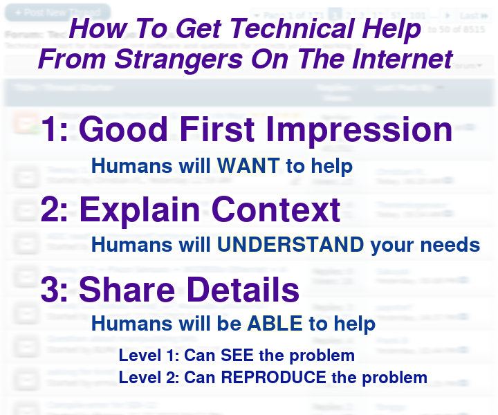
Good First Impression

“You get 1 chance to make a good first impression” is timeless wisdom. Strangers will quickly form an opinion of you, based only on the words, images or video in your message.  Make your words count!

Showing you’ve made an effort, more than any other factor, will influence people to help.

But if you’re an absolute beginner, what sort of effort can reasonably be expected?  Anyone can try a Google search using the words from their question.  Many experts have long forgotten how difficult finding relevant info can be when you don’t know the proper terms, or unrelated tech has since started using those words.  Just explaining the search you tried and confusing or off-topic info you’ve seen can go a long way towards helping seasoned experts to understand your struggle.  The results aren’t important, your personal effort is what matters!

Genuine interest to learn also tends to make a good impression.  Even a few words can really communicate your attitude.  Frustrated but determined to learn from a trying experience can make a great impression.  Very smart people who can help the most tend to appreciate genuine & candid communication.

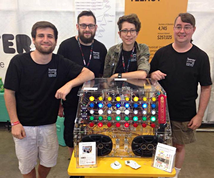
Of course if you have started a project or done work, mention it.  Or better, show what you have tried.  Screenshots, photos or even a quick video can powerfully demonstrate what you’ve done, and cover the other 2 aspects of a successful forum question.

Even just a few extra words, which show you are making a sincere effort and sincerely wish to learn, can make an improvement in the response you’ll likely receive.

Context Brings Understanding

Humans have amazing capability to genuinely understand.  Experts can sometimes apply their tremendous knowledge towards creative ideas to solve your problem… when they actually understand what you really need.

Providing context in your question is key.  What are your larger goals?  How does the question you’re asking fit into your project?  What do you ideally hope to accomplish?  And why?

When working on a technical matter, it’s easy to focus on only the issue at hand.  Remember, good people with vast knowledge & experience regularly read forums, just because they enjoy helping others.  When composing your forum question, don’t forget to give context.  It can make the difference between answers that are at best technically correct and answers that are truly insightful.

Details Are Essential

Modern technical issues can involve a mind boggling number of details.  How much raw information should your question include?  Before posting, try asking these questions:

  1. Can readers SEE or EXPERIENCE your problem?
  2. Can readers REPRODUCE your problem?

It’s easy to joke “I saw an error, but clicked OK without reading”.  But seriously, a basic level of detail allows everyone reading your message to see the problem.  A screenshot or exact copy of an error, plus specific information about software, hardware, and steps taken are a baseline for your readers to merely attempt to see the problem as you did.

Ideally, people reading your message would be able to reproduce the problem.  Providing this level of detail is not always practical.  But if you can give enough info, odds of someone solving the problem are vastly improved.

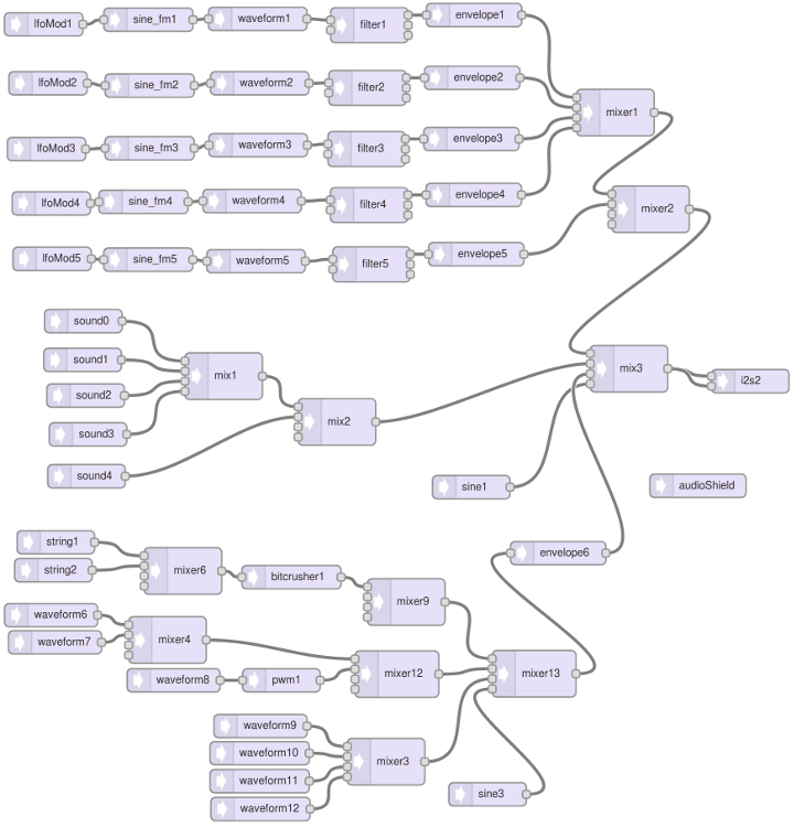
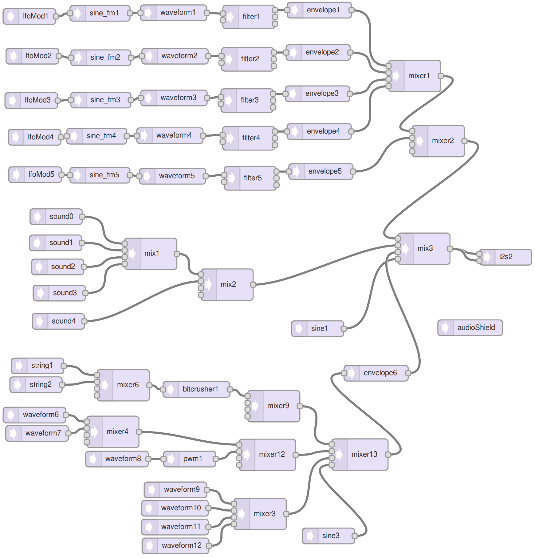
Software programming questions should include complete source code, not merely the small fragments.  Often code issues involve subtle details, such as declarations of variables elsewhere in the code.  Some experts can spot these sorts of problems with amazing speed, if you show complete code!  Don’t forget to be specific about any extra libraries used.

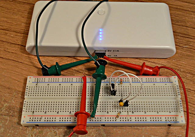
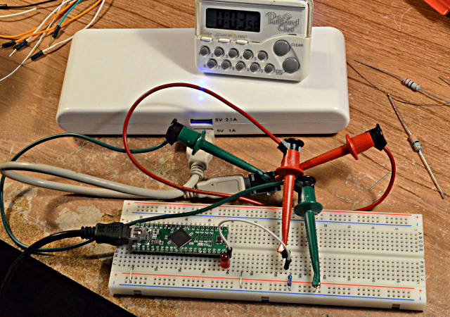
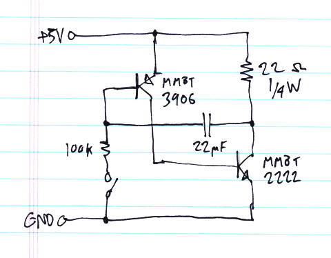
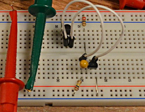
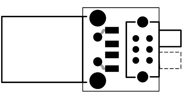
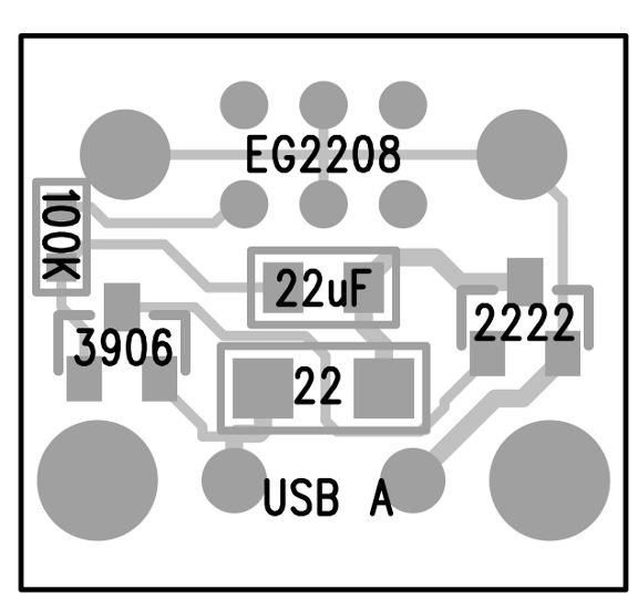
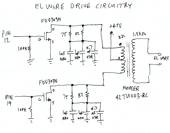
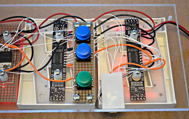
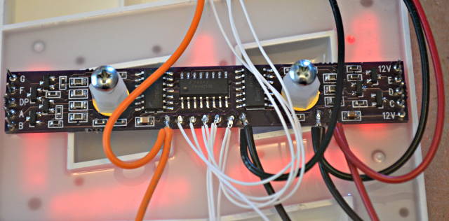
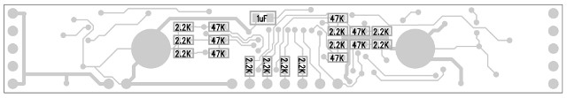
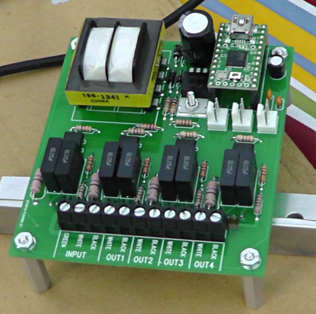
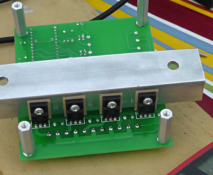
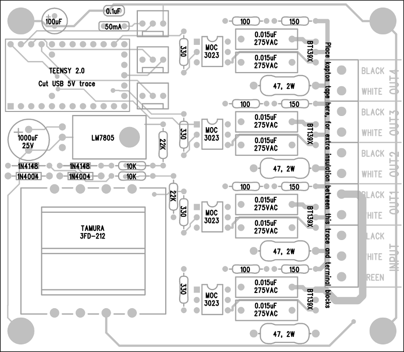
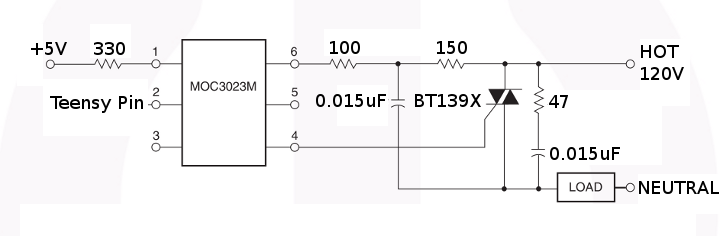
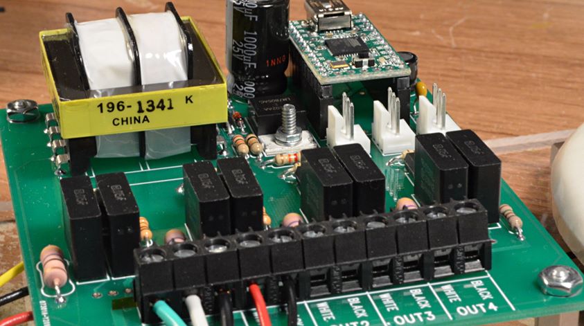
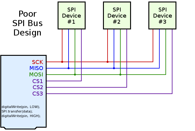
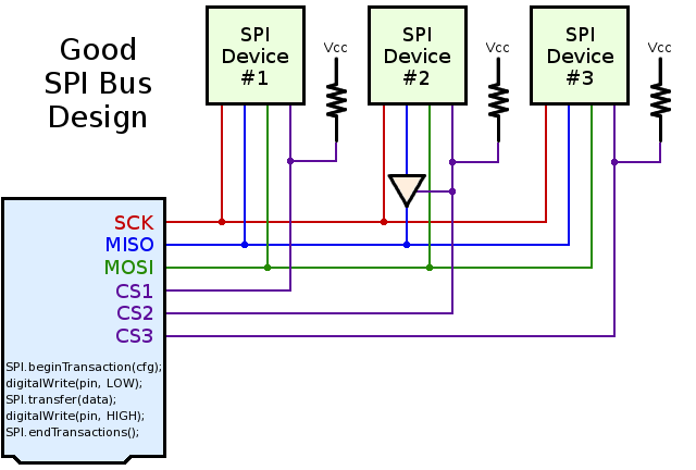
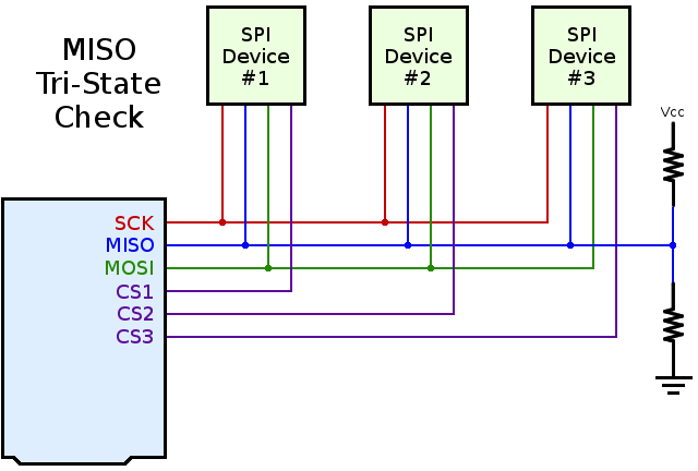
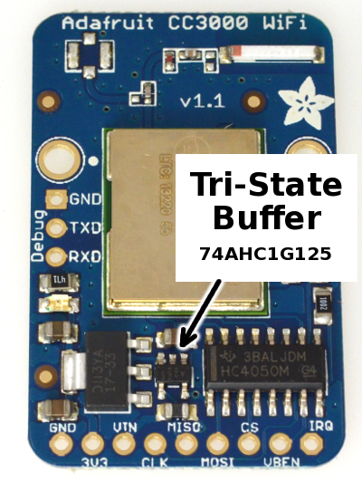
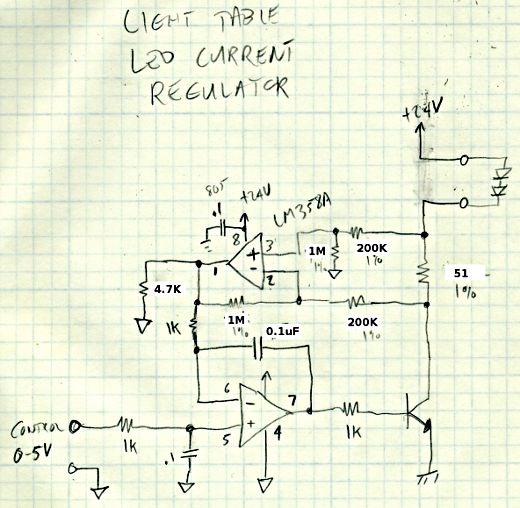
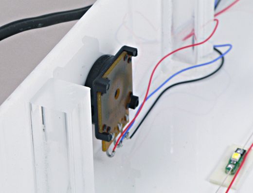
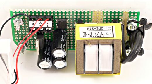
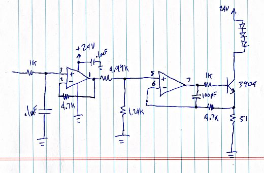
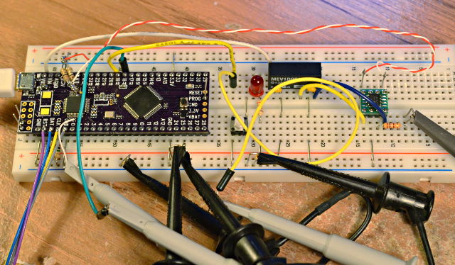
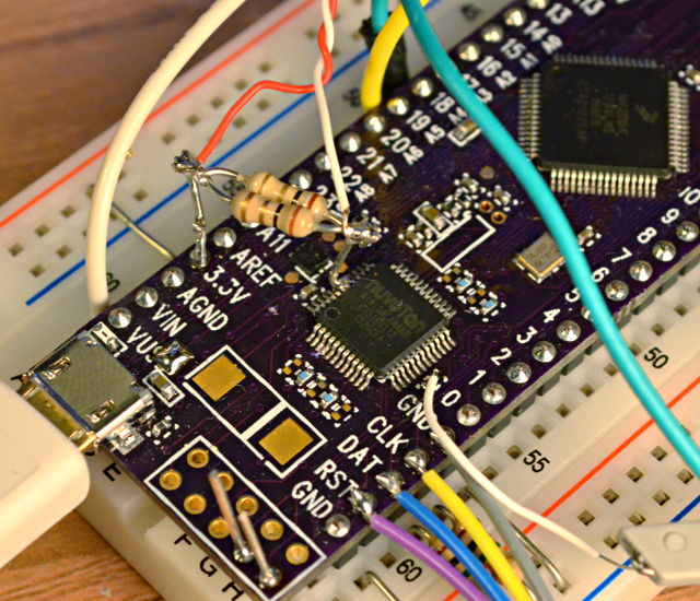
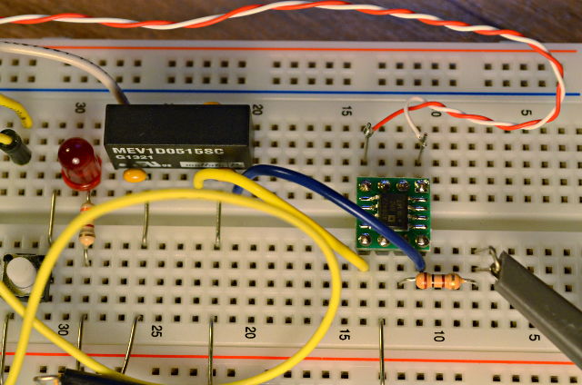
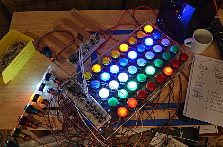
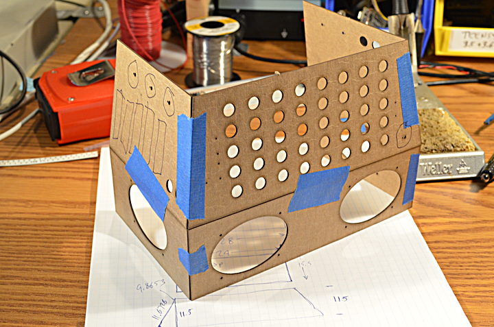
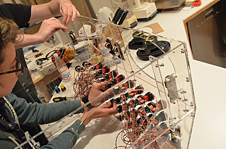
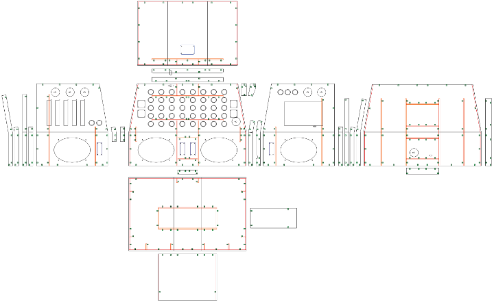
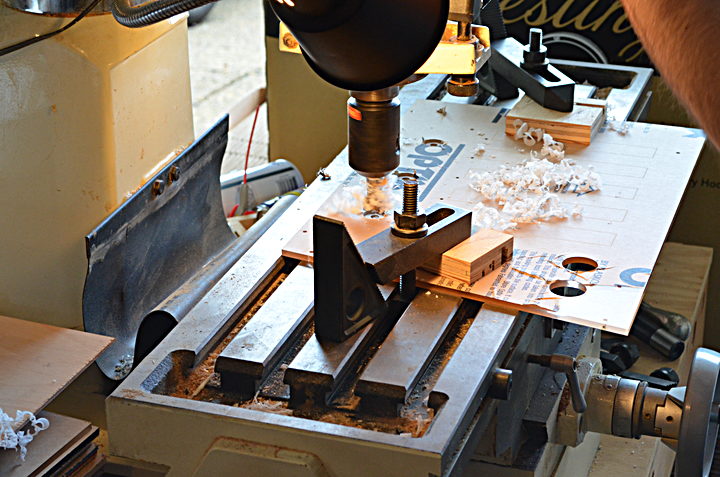
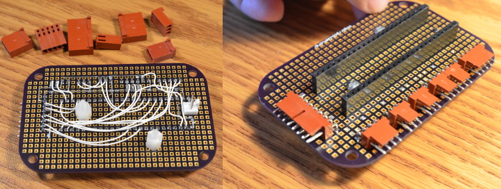
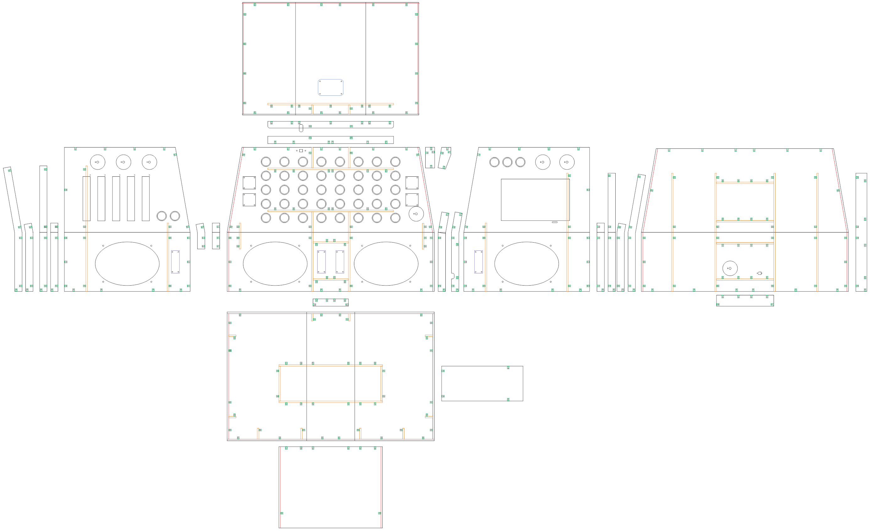
Electronic hardware issues usually need photos or accurate wiring diagrams, and links or part numbers of materials used.

It’s common to feel nervous or self-conscious about showing your project details on a forum.  Don’t be shy.  Experts who regularly read the forum genuinely want to help.  Show enough detail, give context and demonstrate you’ve made some effort and odds very good they will help!

Common Pitfalls

Forums don’t always work ideally.  Usually the 3 steps above will lead to good results, but there are a number of common problems to keep in mind.

Too Much Diagnosis

Technical problem solving involves observing the effects of an issue and trying to deduce the cause.  A very natural human tendency writing while in this mindset is to focus moreso on the presumed causes than objectively sharing the observed effects.

Usually a short break between an intense debugging session and composing your forum post can make a tremendous difference.  When writing, try to think of your reader’s perspective.  Are you asking people to help diagnose the problem, or merely asking them to nod “yup, you’re right” in agreement with your existing conclusions?

However, sharing your thought process can avoid people needlessly covering the same ground you’ve already investigated.  There is no one perfect way.  Just keep in mind that too much diagnosis can shut people out of helping you troubleshoot.

Venting Frustration

Let’s face it, some technical problems are really hard, even intensely frustrating.  When you’re annoyed, venting frustration is a very natural human tendency.

Before you post on a forum, creating that all-important first impression with strangers, review your message.  Some level of expressed frustration is normal and maybe even helpful.  It can show you’ve really tried.  Just beware the common trap, where your forum message ends up being perceived as a rant rather than a question or request for help.

Nobody Replies

Even under ideal conditions, sometimes forum posts get no replies.  This can feel disappointing & disheartening.  Try not to let that emotion take control as you compose a reply to “bump” the thread.  You can do much better.

Effort matters.  If days or weeks have elapsed since your first post, presumably you’ve put more effort into the project?  Even if fruitless, the personal effort you’ve invested since your prior post is something you can share that tends to draw people in.  Photos or code or other clear signs of work on your part can be highly effective.

Sometimes very difficult questions, with plenty of detail, get no replies simply because nobody knows the answer.  Or nobody knows with certainty.  Asking for opinions or ideas for directions to try can really help in these cases, turning what started as a solid question into a more fluid conversation.  Again, apparent effort is the key factor that attracts people to contribute towards helping solve a tough problem.

Most forums discourage or even ban posting duplicate copies of your question, or “cross posting”.  Posting the exact same message in multiple places at the same time is almost never a good idea.  Experts who regularly read the forums, the people most likely to help you, will almost certainly notice.  You get one chance to make a good first impression.  However, after a period with no answers, sometimes duplicate posting can be done gracefully, usually with an explanation & link to the prior unanswered question.

Academically Dishonest Students

Every tech forum gets lazy students asking people to do their homework.  Experts who regularly read forums are inundated by these low-quality questions.  Like an email inbox with spam, the last thing you want is your message to be mistaken for more junk & quickly dismissed.

If you are doing a student project, usually the best approach is to be honest about the academic nature (and deadline) and to make sure your sincere effort shines through.  Earnest effort and genuine desire to learn is what distinguishes good students in the minds of experts who will actually help!

Proprietary Projects

When you can’t share source code or other relevant technical details, technical forum help is rarely effective.

Usually you must invest extra effort to separate just the one piece that is problematic from the rest of your project, so it can be shared.  If you have not done this, consider that asking “has anyone seen a problem like XYX” is essentially asking humans to function as a search engine.  Sometimes the results are good (better than you could do with Google), but difficult technical problems without sharing relevant details are rarely solved by blind guessing.

If your employer or organization absolutely will not allow any code or details shared, no matter how trivial, perhaps using “enterprise” products which come with support contracts, or hiring a private consulting firm is more appropriate than asking on a public forum.

After Your Question Is Answered

The best way to say “Thank You” is to acknowledge who had the right answer.  Many experts pour countless unpaid hours into helping strangers on forums, simply because it feels good to be helpful.  Being recognized as supplying the correct answer is a nice reward.

When your problem is solved, please consider Google and other search engines may send people with similar technical questions to your messages for years to come.  The very best thing you can do after a technical problem is resolved is a quick but clear message confirming the solution.

If you posted on multiple forums, please take a few minutes to follow up on every thread with a link to the message with best answer.

About This Article (and Me)

Over the last 6 years, I’ve written 18620 answers our forum here at PJRC, and many more on numerous other forums.  During this time, we’ve managed to grow a pretty good forum community and help many thousands of people with projects.

I watched and tried to learn which what has worked and how we might improve.  One thing that’s become very clear is so many people need a little guidance on how to best ask their questions.  It’s not the technical nature, but these subtle human factors that matter most.

My hope is to see all tech forums improve.  Please, share this article.

-Paul Stoffregen


LED Gyro Sphere

NZDoug made a cool interactive LED sphere using gyro and sound sensors.

This nifty LED sphere has multiple sensors to make it interactive.  It features a gyro board and audio mice controlling 130 addressable LEDs.  The project uses takes advantage of the processing power and memory of the Teensy 3.6.

There are menu buttons on the sphere used to select up to 9 different effects:

  1. Gyro Color – Rotating sphere will change color of all LEDs
  2. Gyro Puzzle – Three Bands of color set by X, Y, Z axis control of the Gyro. The objective is to rotate the ball until all bands are the same color.
  3. Sound Meter – All LEDs (Great next to a Blue Tooth Speaker!!)
  4. Sound Meter – Single VU Meter with 130 LEDs spiraling down
  5. Dot Snakes Sound – 4 snakes run around sphere and change speed with sound
  6. Dot on Top – Gyro keeps color dot on top of the sphere when sphere rolled on floor
  7. Colorwash – Beautiful effect of all colors cycled through on sphere
  8. Dot Snakes – 4 snakes run around sphere at constant speed
  9. Gyrosnake – Sound changes color as LEDs spiral downward

Code, schematics, and build details are available both on the Hackster.io project page and Instructables

Hut’s Anti-Hug Hat

Rolf Hut made an awesome Anti-Hug Hat, or personal space protector, for Burning Man this year.

The Dutch scientist wanted to explore working with Teensys and APA102 LEDs – and wanted a way to try to avoid the typical American hug at Burning Man, so he came up with the Anti-Hug Hat.  The hat has acoustic distance sensors around it an when an object (like a person) gets too close, the ring of LEDs around the hat change from green to orange to red.

Teensyduino 1.43 Released

Today PJRC is releasing Teensyduino version 1.43.

The 1.43 installers are available now at the downloads page.

Arduino 1.8.6 Support

The main new feature in 1.43 is support for Arduino 1.8.6.  The main reason to upgrade is 1.8.6 can compile your code significantly faster.

Arduino 1.8.6 is the first non-beta Arduino IDE to support parallel compile.  If your computer has a quad-core processor, when rebuilding all files, Arduino may compile up to 4 pieces of code at the same time.  Usually the speed increase is much less than 4 times faster, but still it manages to compile code in much less time than running every compiler process 1 at a time.

When you change boards or settings, a full rebuild of all libraries files must be done for all library files your code uses.  Arduino 1.8.2 to 1.8.5 would often do this full rebuild unnecessarily, especially if you edited any of the library files (not in the Arduino IDE’s editor).  1.8.6 fixes this unnecessary rebuilding.

However, not everything is perfect with 1.8.6.  Several bugs were discovered after release which cause 1.8.6 to crash, especially if certain data files are corrupted.  Teensyduino 1.43 includes fixes for a couple of these bugs.  The rest will be fixed in Arduino 1.8.7, which may appear soon.  When it does, of course we’ll release Teensyduino 1.44 to support it.

Headless Install

The installer now support a “headless” command line install.  This can be useful if you wish to create scripts to automatically install Teensyduino.  The main intended use is for Continuous Integration testing with systems such as Travis-CI.

Run the installer with –dir=<directory> to specify the Arduino install location.  Using this option cases the installer to run automatically without the GUI.

Adafruit has offered to include Teensy in their automated testing script.  Soon this will allow Teensy to be automatically tested (at least to verify libraries compile without error) for all of Adafruit’s libraries!

Bugs Fixed

Several issues are fixed in version 1.43.

  • Fix default Ethernet CS pins on Teensy 2.0 & Teensy++ 2.0.  Old versions of Ethernet would default to the “SS” pin on AVR chips, and if you wanted any other pin your only option was to edit the Ethernet library code!  With the addition of Ethernet.init(pin), you could choose which pin to use, but this change also caused the default to become pin 10, even if SS was a different pin on your board (as it is with Teensy 2.0 & Teensy++ 2.0).  Now the default is restored to the actual SS pin, and you can use Ethernet.init(pin).
  • Fix USB Keyboard ‘#’ for UK & Irish layouts.
  • Generic UDP class support beginMulticast.  Some libraries using multicast need this defined in the board’s core library.
  • Fix USB MIDI hogging transmit buffers.  If you used USB MIDI together with USB Serial or other USB communication, and you transmit USB MIDI messages faster than your computer can process, previously the MIDI message could consume all the USB buffer memory.  This fix prevents MIDI from hogging all the buffers, so the other non-MIDI communication (hopefully) will not stall.
  • Fix FreqCount for use at high frequencies.  A bug which caused very infrequent errors when measuring very high frequencies has been fixed.
  • Fix SerialPlotter for Ports(Teensy).  Previously Arduino’s Serial Plotter would only work if you had selected Tools > Ports from the “Serial” section of the menu.  Now the “Teensy” ports section is fully supported.  When using a “Teensy” port, board disconnect and reconnect are supported.  The plot restarts from zero when you plug the cable in.  Proper stop and restart is also supported when you upload new code.
  • USBHost_t36 fix for Gigabyte keyboard (thanks KurtE).  These special gaming keyboards with “N Key Rollover” should now work.
  • OctoWS2811 update movie2serial.pde for compatibility with Processing 3.4.  This program streams video to large LED projects.  Minor updates were needed to work with the newest version of Processing and its video library.
  • Remove BYTE define.  This was previously included in Teensyduino for pre-1.0 Arduino compatibility.  But some libraries and code tend to use “BYTE” for their own constants and variables, causing a conflict.  This feature for compatibility with ancient Arduino libraries was causing more harm than good.  It’s been removed.
  • Update WS2812Serial documentation.  A mistake in the documentation showed an extra pin, which was never actually supported and can’t work due to hardware limitation.
  • Improve installer help dialog on Windows.  The “Windows App” incompatible with Teensyduino.  The installer now mentions this in the “?” help dialog.
  • Workaround a rare USB buffering issue.  During sustained fast data transfer from a PC to Teensy, a rare bug could cause wrong data to be received after many megabytes of transfer.  A workaround was added to prevent this problem.  Special thanks to Trammell Hudson for providing a test case.
  • Fix for Arduino 1.8.6 startup (Arduino issue #7917).  If any library you have installed has a version number which Arduino 1.8.6 can’t understand, the IDE crashes at startup.  A fix for this problem is included, so you aren’t left with the software unable to run if you have a “bad” library installed.
  • Add Arduino’s fix for slow 1.8.6 menus on Mac (Arduino issue #7935).  Newer versions of Java on Macintosh are much slower to create menus.  The Arduino developers worked around this problem by creating the menus only once, and they’re merely modified when changes are needed.  Teensyduino 1.43 adds this fix to your copy of 1.8.6.