Touch Piano DIY Circuit Board

Michael Sobolak made a cool little DIY touch piano.

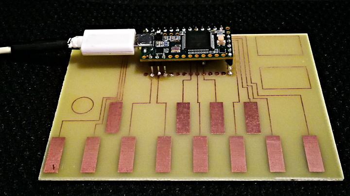
Michael made this cool little MIDI Controller by first etching his own PCB that he designed in Illustrator using printer toner transfer and copper etching solution.  There’s a bit of tricky soldering to the TouchSense inputs on the bottom of the Teensy, but the rest of the soldering is pretty simple.

Abelton Live was used for the sound libraries for this project, but it should also work with Garage Band or other digital audio workstation (DAW).

Code for the project can be found on this Instructibles page.


Genesynth

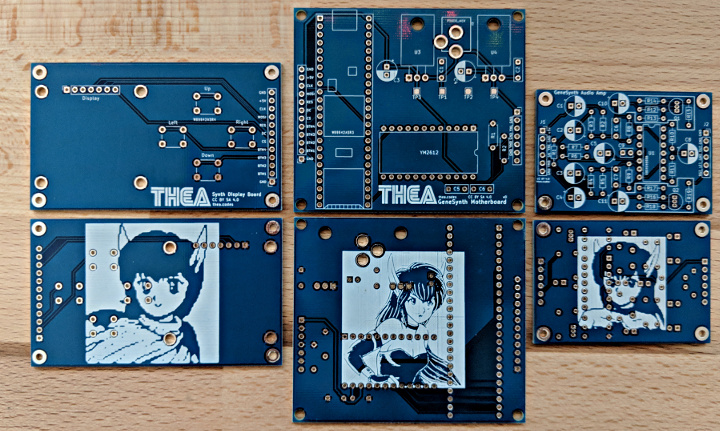
Thea Flowers built a really cool Sega-Genesis inspired synthesizer, the Genesynth.

Thea had been toying around with building a synthesizer for a while but was lacking inspiration, then she came up with the idea to build a synth using the same chip as the Sega Genesis.  The Genesis was one of the last consoles to feature a synthesizer instead of samples and CD playback.  This created the distinctive sound of the soundtracks to their iconic games.

The Genesynth uses the Yamaha YM2612 FM syntheses chip, the same chip used in the Sega Genesis.  A Teensy 3.5 interfaces between the chip and a USB-MIDI connection.  A high-quality audio amplifier was used.  While it’s far better than the original Genesis amplifier, it still retains the same filter roll-off so you can hear the chip’s9-bit DAC’s distortion.

Thea says that the project took weeks of research, months of iteration, and nearly a year of programming.  This was not only her first synthesizer build, but her also her first hardware build.  It also gave her the opportunity to learn to make PCBs, which she did with style.

This Twitter Moment is a collection of her Tweets about the project.  It includes some short audio clips so you can hear the Genesynth in action.

She has some great blog posts about the build process, including the Research, Basic Communication, Proper Audio, and PCBs and Noise Elimination.

You can also read a write of the project over on Hackster.io

Finally, all build information including code and PCBs files are available on GitHub.

Embrace Heart Sequenced Incandescent Light Dimming

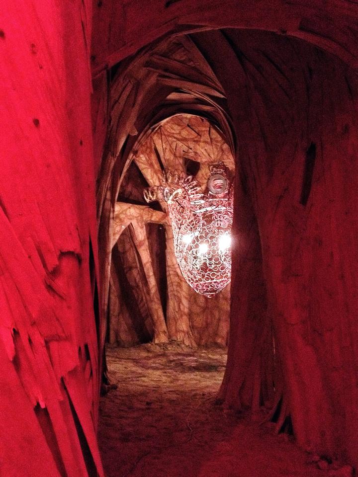
I worked on a tiny piece of the Embrace sculpture at Burning Man 2014.

Inside were 2 hearts, one made here in Portland by Lostmachine Andy & others at Flat Rat Studios.  I made electronics to gradually fade 4 incandescent light bulbs in heart beating patterns.

These wonderful photos where taken by Sarah Taylor.

Inside the enormous sculpture were two hearts.  The blue on was built by a group in Vancouver, B.C., Canada, and of course this one was built here in Portland, Oregon, USA.

Andy wanted this heart to have a very warm, gentle atmosphere, with warn incandescent bulbs slowly fading to create the heart beat.  These effect turned out quite well.  Andy really knows his stuff!

Here’s a great time-lapse video where you can see the slow, gradual incandescent light fading as a rapid heart beat.  Skip forward to about 0:36 in this video.


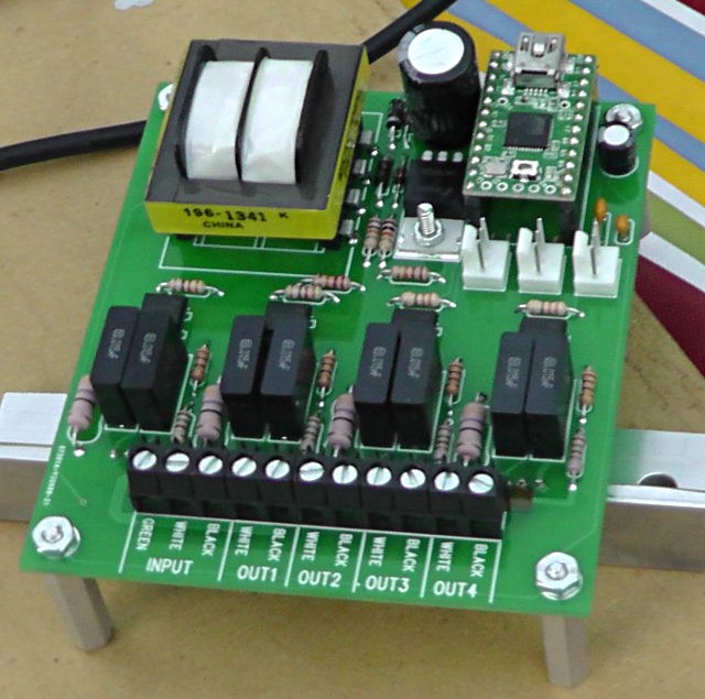
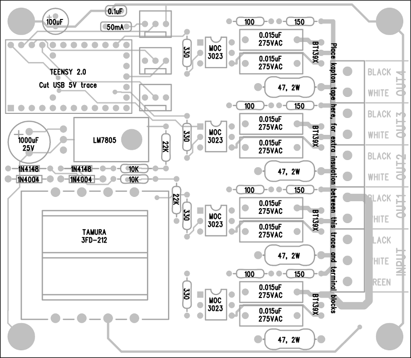
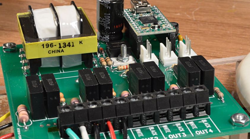
The light fading was done using a Teensy-based 4-channel AC dimmer board, on this 4 by 3.5 inch circuit board.

Here’s a quick video, from the first test of the light controller.

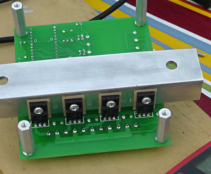
Four BT139X Triacs that actually switch the AC voltage are mounted on the bottom side to a heatsink that’s meant to dissipate any heat to the metal case.  Originally Andy believed the lights might be 500 watts each, so I was concerned about heat.  In the end, four 60 watt bulbs were used and the Triacs did not get noticeably warm.

Here is a parts placement diagram for building the circuit board.  Two boards were built, the one that ran the project and a spare… just in case!

The PCB cad files are attached below, if anyone wants to make more of these boards.

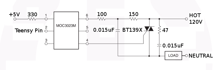
The AC switching circuitry was basically Fairchild Semiconductor’s recommended circuit for the MOC3023 optical isolator, which allows a Teensy 2.0 board to safely control the AC voltage.  Four copies of this circuit were built on the board.

This circuit requires the Teensy 2.0 to know the AC voltage timing, so it can trigger the Triac at the right moment.  Triggering early in the AC waveform causes the Triac to conduct near the full AC voltage for maximum brightness.  Triggering later reduces the brightness.

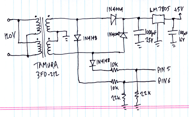
To get the AC timing, I built this special power supply onto the board.

The Teensy 2.0 receives pulses on pins 5 and 6 as the AC waveform cycles positive and negative.

One caveat is this approach depends on the AC voltage being a sine wave.  The AC voltage was one of the first questions I asked Andy, and he was told Burning Man would supply a true sine wave AC voltage.  When he got out there, it turned out the power was actually a “modified sine wave”, which really isn’t anything like a sine wave.  This circuit didn’t work well.  Fortunately, they were able to run the lighting from a small generator that produced a true sine wave.

With the AC timing arriving on pins 5 and 6, and 4 pins able to trigger Triacs, and 3 pins connected to analog voltages for changing speed, brightness and pattern, the only other major piece of this technology puzzle is the software.

In this code, loop() tracks the changes in the waveform on pins 5 & 6, and it fires the Triacs at their programmed times.  120 times per second (each AC half cycle), the recompute_levels() function runs, which reads the analog controls and changes the Triac time targets, which loop() uses to actually control the voltage outputs.

Here’s all the code:

void setup()
{
	pinMode(0, INPUT_PULLUP);	// unused
	pinMode(1, INPUT_PULLUP);	// unused
	pinMode(2, INPUT_PULLUP);	// unused
	pinMode(3, INPUT_PULLUP);	// unused
	pinMode(4, INPUT_PULLUP);	// unused
	pinMode(5, INPUT);		// Phase A
	pinMode(6, INPUT);		// Phase B
	pinMode(7, INPUT_PULLUP);	// unused
	pinMode(8, INPUT_PULLUP);	// unused
	pinMode(9, INPUT_PULLUP);	// unused
	pinMode(10, INPUT_PULLUP);	// unused
	digitalWrite(11, LOW);
	pinMode(11, OUTPUT);		// LED
	digitalWrite(12, HIGH);
	pinMode(12, OUTPUT);		// trigger4, low=trigger
	digitalWrite(13, HIGH);
	pinMode(13, OUTPUT);		// trigger3, low=trigger
	digitalWrite(14, HIGH);
	pinMode(14, OUTPUT);		// trigger2, low=trigger
	digitalWrite(15, HIGH);
	pinMode(15, OUTPUT);		// trigger1, low=trigger
	pinMode(16, INPUT_PULLUP);	// unused
	pinMode(17, INPUT_PULLUP);	// unused
	pinMode(18, INPUT_PULLUP);	// unused
	analogRead(19);			// pot #3
	analogRead(20);			// pot #2
	analogRead(21);			// pot #1
	pinMode(22, INPUT_PULLUP);	// unused
	pinMode(23, INPUT_PULLUP);	// unused
	pinMode(24, INPUT_PULLUP);	// unused
}


uint8_t pot1=0, pot2=0, pot3=0;
uint8_t level1=100, level2=128, level3=0, level4=250;


uint8_t phase_to_level(uint16_t phase)
{
	uint16_t amplitude;

	// 10923 = 32768 / 3
	//     0 to 10922 = increasing: 0 -> 32767
	// 10923 to 21845 = decreasing: 32767 -> 0
	// 21846 to 32768 = increasing: 0 -> 32767
	// 32769 to 43691 = decreasing: 32767 -> 0
	// 43692 to 65535 = resting: 0

	if (phase < 10923) {
		amplitude = phase * 3;
	} else if (phase < 21845) {
		phase = phase - 10923;
		phase = 10922 - phase;
		amplitude = phase * 3;
	} else if (phase < 32768) {
		phase = phase - 21846;
		amplitude = phase * 3;
	} else if (phase < 43691) {
		phase = phase - 32769;
		phase = 10922 - phase;
		amplitude = phase * 3;
	} else {
		amplitude = 0;
	}
	//amplitude = (phase < 32768) ? phase : 65535 - phase;
	amplitude >>= 6;  // range 0 to 511
	amplitude *= (pot2 + 84) / 6;  //
	amplitude += 6000 + pot2 * 8; // minimum brightness
	return (amplitude < 32768) ? amplitude >> 7 : 255;
}

void recompute_levels()
{
	static uint16_t phase=0;
	static uint8_t n=0;

	analog_update();
	//Serial.print("pot: ");
	//Serial.print(pot1);
	//Serial.print(", ");
	//Serial.print(pot2);
	//Serial.print(", ");
	//Serial.print(pot3);
	phase += (((uint16_t)pot1 * 83) >> 5) + 170;
	//Serial.print(", phase: ");
	//Serial.print(phase);
	if (pot3 < 128) {
		level1 = phase_to_level(phase);
		level2 = level1;
		level3 = phase_to_level(phase + pot3 * 52);
		level4 = level3;
	} else {
		uint16_t n = (pot3 - 127) * 26;
		level1 = phase_to_level(phase);
		level2 = phase_to_level(phase + 6604 - n);
		level3 = phase_to_level(phase + 6604);
		level4 = phase_to_level(phase + 6604 + n);
	}
	//Serial.print(", levels: ");
	//Serial.print(level1);
	//Serial.print(", ");
	//Serial.print(level2);
	//Serial.print(", ");
	//Serial.print(level3);
	//Serial.print(", ");
	//Serial.print(level4);
	//Serial.println();
}


void loop()
{
	uint8_t a, b, prev_a=0, prev_b=0, state=255, triggered=0;
	uint32_t usec, abegin, bbegin, alen, blen;
	uint16_t atrig1, atrig2, atrig3, atrig4;
	uint16_t btrig1, btrig2, btrig3, btrig4;
	bool any;

	while (1) {
		// read the phase voltage and keep track of AC waveform timing
		a = digitalRead(5);
		b = digitalRead(6);
		if (a && !prev_a) {
			// begin phase A
			usec = micros();
			if (state == 0) {
				state = 1;
				abegin = usec;
				triggered = 0;
				Serial.print("A");
				Serial.println(usec);
			} else if (state == 255) {
				state = 11;
				abegin = usec;
			} else {
				state = 255;
			}
		}
		if (!a && prev_a) {
			// end phase A
			usec = micros();
			if (state == 1) {
				state = 2;
				alen = usec - abegin;
				Serial.print("a");
				Serial.print(usec);
				Serial.print(",");
				Serial.println(alen);
				if (alen < 12000) {
					// compute trigger offsets for next A phase
					recompute_levels();
					atrig1 = level1 ? ((256 - level1) * alen) >> 8 : 30000;
					atrig2 = level2 ? ((256 - level2) * alen) >> 8 : 30000;
					atrig3 = level3 ? ((256 - level3) * alen) >> 8 : 30000;
					atrig4 = level4 ? ((256 - level4) * alen) >> 8 : 30000;
				} else {
					state = 255;
				}
			} else if (state == 11) {
				state = 12;
				alen = usec - abegin;
			} else {
				state = 255;
			}
		}
		if (b && !prev_b) {
			// begin phase B
			usec = micros();
			if (state == 2) {
				state = 3;
				bbegin = usec;
				triggered = 0;
				Serial.print("B");
				Serial.println(usec);
			} else if (state == 12) {
				state = 13;
				bbegin = usec;
			} else {
				state = 255;
			}
		}
		if (!b && prev_b) {
			// end phase B
			usec = micros();
			if (state == 3) {
				state = 0;
				blen = usec - bbegin;
				Serial.print("b");
				Serial.print(usec);
				Serial.print(",");
				Serial.println(blen);
				if (blen < 12000) {
					// compute trigger offsets for next B phase
					recompute_levels();
					btrig1 = level1 ? ((256 - level1) * blen) >> 8 : 30000;
					btrig2 = level2 ? ((256 - level2) * blen) >> 8 : 30000;
					btrig3 = level3 ? ((256 - level3) * blen) >> 8 : 30000;
					btrig4 = level4 ? ((256 - level4) * blen) >> 8 : 30000;
				} else {
					state = 255;
				}
			} else if (state == 13) {
				state = 0;
				blen = usec - bbegin;
			} else {
				state = 255;
			}
		}
		prev_a = a;
		prev_b = b;

		// trigger triacs at the right moments
		if (state == 1) {
			usec = micros();
			any = false;
			if (!(triggered & 1) && usec - abegin >= atrig1) {
				digitalWrite(15, LOW);
				triggered |= 1;
				any = true;
				//Serial.println("trig1(a)");
			}
			if (!(triggered & 2) && usec - abegin >= atrig2) {
				digitalWrite(14, LOW);
				triggered |= 2;
				any = true;
				//Serial.println("trig2(a)");
			}
			if (!(triggered & 4) && usec - abegin >= atrig3) {
				digitalWrite(13, LOW);
				triggered |= 4;
				any = true;
				//Serial.println("trig3(a)");
			}
			if (!(triggered & 8) && usec - abegin >= atrig4) {
				digitalWrite(12, LOW);
				triggered |= 8;
				any = true;
				//Serial.println("trig4(a)");
			}
			if (any) {
				delayMicroseconds(25);
				digitalWrite(15, HIGH);
				digitalWrite(14, HIGH);
				digitalWrite(13, HIGH);
				digitalWrite(12, HIGH);
			}
		} else if (state == 3) {
			usec = micros();
			any = false;
			if (!(triggered & 1) && usec - bbegin >= btrig1) {
				digitalWrite(15, LOW);
				triggered |= 1;
				any = true;
				//Serial.println("trig1(b)");
			}
			if (!(triggered & 2) && usec - bbegin >= btrig2) {
				digitalWrite(14, LOW);
				triggered |= 2;
				any = true;
				//Serial.println("trig2(b)");
			}
			if (!(triggered & 4) && usec - bbegin >= btrig3) {
				digitalWrite(13, LOW);
				triggered |= 4;
				any = true;
				//Serial.println("trig3(b)");
			}
			if (!(triggered & 8) && usec - bbegin >= btrig4) {
				digitalWrite(12, LOW);
				triggered |= 8;
				any = true;
				//Serial.println("trig4(b)");
			}
			if (any) {
				delayMicroseconds(25);
				digitalWrite(15, HIGH);
				digitalWrite(14, HIGH);
				digitalWrite(13, HIGH);
				digitalWrite(12, HIGH);
			}
		}
	}
}


#define ADMUX_POT1  0x60
#define ADMUX_POT2  0x61
#define ADMUX_POT3  0x64
void analog_update()
{
	static uint8_t count=0;

	switch (count) {
	  case 0: // start conversion on pot #1
		ADMUX = ADMUX_POT1;
		ADCSRA |= (1<<ADSC);
		count = 1;
		return;
	  case 1: // read conversion on pot #1
		if (ADCSRA & (1<<ADSC)) return;
		pot1 = ADCH;
		ADMUX = ADMUX_POT2;
		count = 2;
		return;

	  case 2: // start conversion on pot #2
		ADMUX = ADMUX_POT2;
		ADCSRA |= (1<<ADSC);
		count = 3;
		return;
	  case 3: // read conversion on pot #2
		if (ADCSRA & (1<<ADSC)) return;
		pot2 = ADCH;
		ADMUX = ADMUX_POT3;
		count = 4;
		return;

	  case 4: // start conversion on pot #3
		ADMUX = ADMUX_POT3;
		ADCSRA |= (1<<ADSC);
		count = 5;
		return;
	  case 5: // read conversion on pot #3
		if (ADCSRA & (1<<ADSC)) return;
		pot3 = ADCH;
		ADMUX = ADMUX_POT1;
		count = 0;
		return;
	  default:
		count = 0;
	}
}


This article was originally published on the DorkbotPDX website, on September 3, 2014.  In late 2018, DorkbotPDX removed its blog section.  An archive of the original article is still available on the Internet Archive.  I am republishing this article here, in the hope it may continue to be found and used by anyone interested in the Embrace art installation or any other project needing sequenced AC light dimming effects.


These comments where written on the old site:


From Brandon:

Once we determined that the AC source was modified sine, I knew there wasn’t anything I could do to help the situation easily in the middle of the desert 🙂
As someone who looked over the board and what not, nice job! Worked really well and looked amazing in operation (on the right power source).

Rev two, perhaps rectified DC drive of the incandescent lights to avoid the modified sine issue? So many folks use those types of inverters to cut costs on big artwork solar installations.

Cheers and thanks for contributing!


From Anonymous:

The embrace structure was prettty cool, I got a chance to explore it at Burninman this year. Wish I got to see it burn down, the videos looked amazing. I assume you guys removed the heart materials before that happened.