Morton Kopf has created a beautiful sequencer that makes drum beats based on Euclidean rhythms.
Euclidean rhythms are an algorithmic way of making beats. Computer scientist Godried Toussaint discovered this technique in 2004, but the algorithm it is based on comes from Euclid, a mathematician in Ancient Greece. Euclid’s algorithm gave us a way of finding the divisor between two integers. Applied musically, that means that a musician could choose the number of steps in a sequence and the number of beats within that sequence, and the algorithm will decide where those beats fall. Layering Euclidean rhythms gives musicians an interesting way of creating intricate polyrhythms, leading to this technique becoming one of the more popular ways of making music with algorithms.
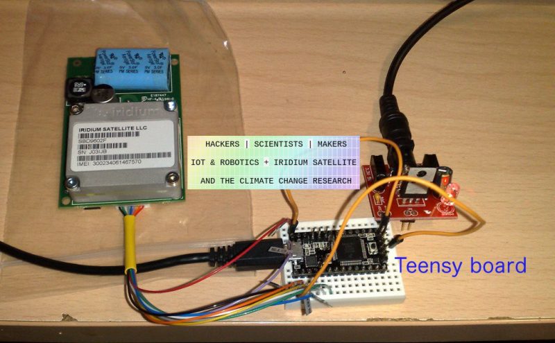
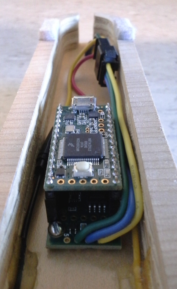
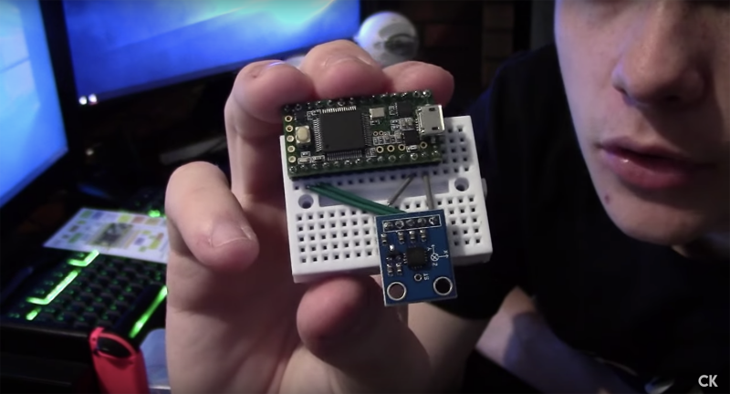
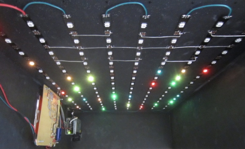
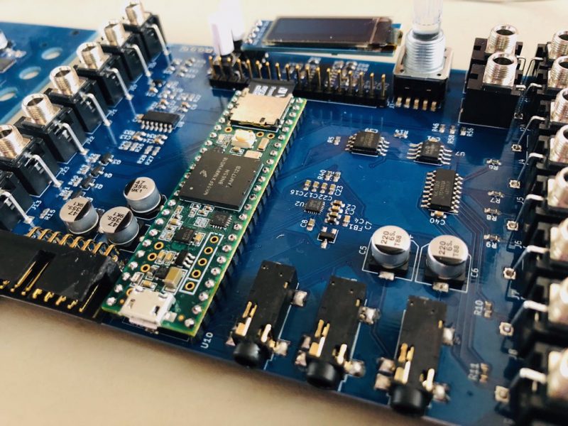
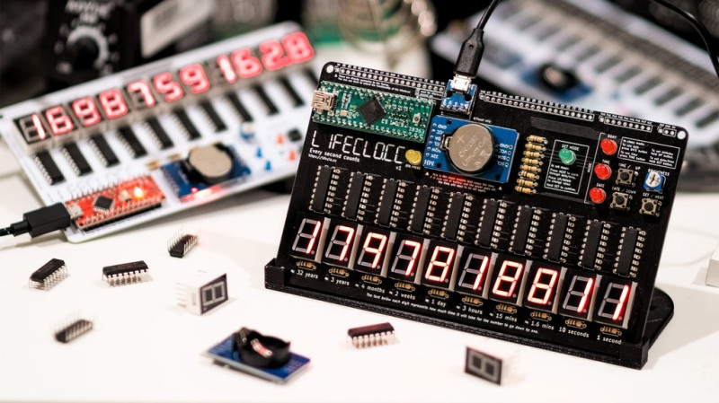
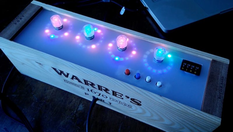
Morton Kopf has made a drum machine that uses these Euclidean rhythms in a four track, 16 step sequencer. It runs on a Teensy 3.5, also using four 16 LED Neopixel rings, four RGB rotary encoders and an LCD screen. Aside from the cool maths behind sequencing, one of best things about this project is the quirky, attractive casing Morton Kopf has made from some frosted perspex and an old port wine case.
If you want to have a go at making your own algorithmic rhythm machine, Morton Kopf has released build instructions on their website, plus you can find all the code for this project on their GitHub. You even also order a DIY kit for your modular synth rack if you don’t want to make the PCB or order the components yourself.