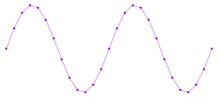
Normally sine waves are generated on microcontrollers using a table lookup.
Lookup tables are perfect when wavelength happens to be an exact multiple of the sample rate, because you never actually need to know the values in between the table’s stored points.
But if you want to generate waveforms at any frequency without changing your sample rate, you end up needing points on the waveform that are between two entries in the table. Four approaches are possible.
With any of these, larger lookup tables give better accuracy. Since sine waves have symmetry, some programmers choose to store only 1/4 of the waveform and add slight overhead to map the other 3 quadrants onto the smaller table.
If you want a sine wave with extremely low distortion, where 16 or 20 or even 24 bits are within +/- 1 from an ideal sine wave, you would need an extremely large table!
Ideally, you’d want to be able to very rapidly compute an accurate sine value for any 32 bit resolution phase angle, so your samples always line up to an ideal sine wave.
Sine can be computed using Taylor series approximation. The formula is: (where x is the angle, in radians)
sin(x) = x – (x^3)/3! + (x^5)/5! – (x^7)/7! + (x^9)/9! – (x^11)/11! + ….
This series goes on forever, but each extra terms makes the approximation rapidly converge to the true value. In doing quite a lot of testing, I discovered the C library function on Linux for sin() uses this approximation, to only the (x^7)/7! term. I also found a few sites talking about going to the (x^9)/9! for “professional quality” audio.
One nice advantage of cutting off the Taylor series with on of the subtracted powers (3, 7, 11, etc) is the tiny remaining error will always be slightly less than the true ideal sine value. This means the final result does not need be checked for greater than 1.00000 and rounded down to fit into the maximum value of an integer.
If you’re still reading by this point, you’re probably shaking your head, thinking this couldn’t possibly be practical in a microcontroller. That’s a complex equation with floating point numbers, and huge values in x^11 and 11!, since 11 factorial happens to be 39916800.
However, this Taylor series equation can be computed very efficiently, by exploiting the Cortex-M4 DSP extension instructions and bit shift operations, where the phase angle from 0 up to 2π is mapped from 0x00000000 to 0xFFFFFFFF.
The code I’m sharing here implements this equation to the (x^11)/11! term using 32 bit integers, using only 12 multiply instructions, which execute in a single cycle on Cortex-M4. The add & subtract take zero CPU time, since those multiply instructions also come in flavors that do a multiply-and-accumulate, either positive or negative accumulate.
The Cortex-M4 multiplies perform a 32×32 to 64 bit multiply, and then discard the low 32 bits, with proper round off. That turns out to be exactly the right thing for managing the huge values of x raised to an increasing power, and the huge numbers of the factorials. Since those divisions are by constants, it’s possible to multiply by the reciprocal to get the same effect.
So, here’s is the optimized code:
https://github.com/PaulStoffregen/Audio/blob/master/synth_sine.cpp#L75
// High accuracy 11th order Taylor Series Approximation
// input is 0 to 0xFFFFFFFF, representing 0 to 360 degree phase
// output is 32 bit signed integer, top 25 bits should be very good
static int32_t taylor(uint32_t ph)
{
        int32_t angle, sum, p1, p2, p3, p5, p7, p9, p11;

        if (ph >= 0xC0000000 || ph < 0x40000000) {
                angle = (int32_t)ph; // valid from -90 to +90 degrees
        } else {
                angle = (int32_t)(0x80000000u - ph);
        }
        p1 =  multiply_32x32_rshift32_rounded(angle << 1, 1686629713);
        p2 =  multiply_32x32_rshift32_rounded(p1, p1) << 3;
        p3 =  multiply_32x32_rshift32_rounded(p2, p1) << 3;
        sum = multiply_subtract_32x32_rshift32_rounded(p1 << 1, p3, 1431655765);
        p5 =  multiply_32x32_rshift32_rounded(p3, p2) << 1;
        sum = multiply_accumulate_32x32_rshift32_rounded(sum, p5, 286331153);
        p7 =  multiply_32x32_rshift32_rounded(p5, p2);
        sum = multiply_subtract_32x32_rshift32_rounded(sum, p7, 54539267);
        p9 =  multiply_32x32_rshift32_rounded(p7, p2);
        sum = multiply_accumulate_32x32_rshift32_rounded(sum, p9, 6059919);
        p11 = multiply_32x32_rshift32_rounded(p9, p2);
        sum = multiply_subtract_32x32_rshift32_rounded(sum, p11, 440721);
        return sum <<= 1;
}
On top of the 12 cycles for multiplies, there’s a few bit shifts, and a quick conditional test which subtracts from a constant. That’s necessary because the Taylor series approximation applies only if the angle is between -pi/2 to +pi/2. For the other half of the sine wave, that subtract maps back into the valid range, because the sine wave has symmetry.
This function takes a 32 bit angle, where 0 represents 0 degrees, and 0xFFFFFFFF is just before 360 degrees. So the input is perfect for a DDS phase accumulator. The output is a 32 bit signed integer, where 0x7FFFFFFF represents an amplitude of +1.0, and 0x80000001 represents -1.0.
This code will never return 0x80000000, so you don’t need to worry about that case.
I did quite a lot of testing while working out these constants and the bit shifts for correct numerical ranges. I believe the top 25 bits are “perfect”. Six of the low 7 bits are very close, but the approximation does diverge slightly as the angle approaches pi/2 magnitude. The LSB is always zero, since the computation needs to have extra overhead range to accommodate values representing up to ~1.57 (pi/2) before the latter terms converge to the final accurate value.
For 8 bit AVR, this approach probably isn’t practical. It probably isn’t practical on Cortex-M0+ either, since there’s no 32×32 multiply with 64 bit result. Cortex-M3 does have such a multiply, but not in the convenient version that rounds off and discards the low 32 bits. On Cortex-M4, this code runs very fast. In fact, when executing at 100 MHz or faster, it might even rival the table lookup, since non-sequential flash accesses (for the table) usually involve a few wait states for a cache miss. Then again, this code does have 6 integer constants, for the conversion to radians and the factorial coefficients… and depending on compiler flags and flash caching behavior, loading those 6 constants might be the slowest part of this algorithm?
I’m sure most people will still use table lookups. Linear interpolation between the nearest 2 table entries is fast and gives a result good enough for most applications. Often a large table is also works well enough, without interpolation. But I wanted to take a moment to share this anyway, even if it is massively overkill for most applications. Hope you find it interesting.