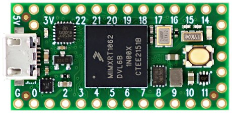
Teensy® 4.0 Development Board
SparkFun is now manufacturing Teensy products. You can buy directly at SparkFun.

|
TEENSY40 | Teensy USB Board, Version 4.0 For prototypes, experimentation, and learning |
|
|
TEENSY40_LOCK | Lockable Teensy USB Board, Version 4.0 For commercial products and secure applications, See Code Security for Lockable Teensy details. |
Recommended Accessories: USB Cable, Pins 14x1 (2)
Sections On This Page:
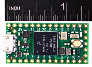
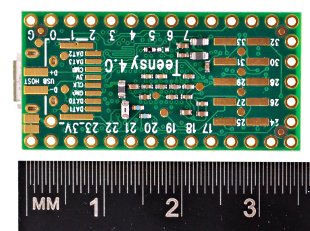
Photos
Specifications
- ARM Cortex-M7 at 600 MHz
- Float point math unit, 64 & 32 bits
- 1984K Flash, 1024K RAM (512K tightly coupled), 1K EEPROM (emulated)
- USB device 480 Mbit/sec & USB host 480 Mbit/sec
- 40 digital input/output pins, 31 PWM output pins
- 14 analog input pins
- 7 serial, 3 SPI, 3 I2C ports
- 2 I2S/TDM and 1 S/PDIF digital audio port
- 3 CAN Bus (1 with CAN FD)
- 32 general purpose DMA channels
- Cryptographic Acceleration & Random Number Generator
- RTC for date/time
- Programmable FlexIO
- Pixel Processing Pipeline
- Peripheral cross triggering
- Power On/Off management
Software
- Arduino IDE + Teensy boards add-on
- Arduino's IDE software with the Teensyduino add-on is the primary programming environment for Teensy. The add-on is installed using Arduino's Boards Manager. Teensy boards add-on includes a large collection of libraries which are tested and optimized for Teensy. Other libraries may be installed manually or by Arduino's library manager.
- Visual Micro
- Visual Micro allows use of Microsoft Visual Studio to program Teensy and many other boards. Only Windows is supported. Visual Micro is commercial paid software.
- PlatformIO
- PlatformIO IDE is a cross platform development environment with many advanced features. Windows, Linux and Macintosh are supported.
- CircuitPython
- CircuitPython provides a .HEX file which you program onto Teensy 4.0 using Teensy Loader. Then Teensy appears to your computer as a USB disk, where copy or save your Python code. CircuitPython does not fully support all of Teensy 4.0's hardware.
- Command Line with Makefile
- Makefiles
for non-graphical use are provided with the Teensyduino installer.
- Teensy 4.x: {Arduino}/hardware/teensy/avr/cores/teensy4/Makefile
- Teensy LC & 3.x: {Arduino}/hardware/teensy/avr/cores/teensy3/Makefile
Processor
- Performance
- ARM Cortex-M7 brings many powerful CPU features to a true real-time microcontroller platform. CPU performance is many times faster than typical 32 bit microcontrollers.
- Dual Issue Superscaler Architecture
- Cortex-M7 is a dual-issue superscaler processor, meaning M7 can execute 2 instructions per clock cycle, at 600 MHz! Of course, executing 2 simultaneously depends upon the compiler ordering instructions and registers. Initial benchmarks have shown C++ code compiled by Arduino tends to achieve 2 instructions about 40% to 50% of the time while performing numerically intensive work using integers and pointers.
- Floating Point Unit
- The FPU performs 32 bit float and 64 bit double precision math in hardware. 32 bit float speed is approximately the same speed as integer math. 64 bit double precision runs at half the speed of 32 bit float.
- Tightly Coupled Memory
- Tightly Coupled Memory is a special feature which allows Cortex-M7 fast single cycle access to memory using a pair of 64 bit wide buses. The ITCM bus provides a 64 bit path to fetch instructions. The DTCM bus is actually a pair of 32 bit paths, allowing M7 to perform up to 2 separate memory accesses in the same cycle. These extremely high speed buses are separate from M7's main AXI bus, which accesses other memory and peripherals.
- Cache
- Two 32K caches, one for instructions and one for data, are used to speed up repetitive access to non-TCM memory.
- Branch Prediction
- Cortex-M7 is the first ARM microcontroller to use branch prediction. On Cortex-M4 & earlier, loops and other code which much branch take 3 clock cycles. With M7, after a loop has executed a few times, the branch prediction removes that overhead, allowing the branch instruction to run in only a single clock cycle.
- Digital Signal Processing
- DSP extension instructions accelerate signal processing, filters and Fourier transform. The Audio library automatically makes uses of these DSP instructions.
Pins
Teensy 4.0 has a total of 40 input/output signal pins. 24 are easily accessible when used with a solderless breadboard.This pinout reference card comes with Teensy 4.0.
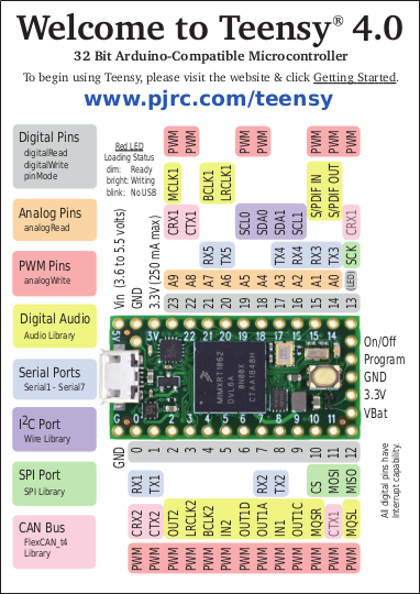
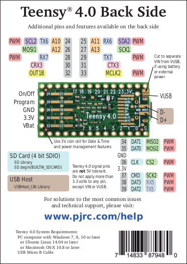
Pinout Card Files:
Front Side (PDF) /
Back Side (PDF)
Not shown on this reference card, Pin 0: CS1, Pin 1: MISO1
A larger, more detailed pinout chart by KurtE is also available on the forum.
Digital Pins
- Digital Input Pins
- Digital pins may be used to receive signals. Teensy 4.0 pins default to INPUT most with a "keeper" resistor. Teensy 4.0 pins accept 0 to 3.3V signals. The pins are not 5V tolerant. Do not drive any digital pin higher than 3.3V.
- Input Pullup / Pulldown / Keeper Resistors
- All digital pins have optional pullup, pulldown, or keeper resistors. These are used to keep the pin at logic HIGH or logic LOW or the same logic level when it is not being actively driven by external circuity. Normally these resistors are used with pushbuttons & switches. The pinMode function with INPUT_PULLUP or INPUT_PULLDOWN must be used to configure these pins to input mode with the built-in resistor.
- Pin Change Interrupts
- All digital pins can detect changes. Use attachInterrupt to cause a function to be run automatically. Interrupts should only be used for clean signals. The Bounce library is recommended for detecting changes on pushbuttons, switches, and signals with noise or mechanical chatter.
- Digital Output Pins
- All digital pins can act at output. The pinMode function with OUTPUT or OUTPUT_OPENDRAIN must be used to configure these pins to output mode. The digitalWrite and digitalToggle functions are used to control the pin while in output mode. Output HIGH is 3.3V. The recommended maximum output current is 4mA.
- Pulse Width Modulation (PWM)
- 31 of the digital pins support Pulse Width Modulation (PWM), which can be used to control motor speed, dim lights & LEDs, or other uses where rapid pulsing can control average power. PWM is controlled by the analogWrite function. 19 groups of PWM can have distinct frequencies, controlled by the analogWriteFrequency function.
- Slew Rate Limiting
- This optional feature greatly reduces high frequency noise when long wires are connected to digital output pins. The rate of voltage change on the pin is slowed. The extra time is only nanoseconds, which is enough to lower undesirable high frequency effects which can cause trouble with long wires.
- Variable Drive Strength
- The output impedance of each digital output may be controlled in 7 steps, ranging from 150 ohms (weakest) up to about 21 ohms (strongest).
- Adjustable Output Bandwidth
- Digital output bandwidth is also programmable, in 4 steps: 50, 100, 150 and 200 MHz.
- LED Pin
- Pin 13 has an orange LED connected. The LED can be very convenient to show status info. When pin 13 is used as an input, the external signal must be able to drive the LED when logic HIGH. pinMode INPUT_PULLUP should not be used with pin 13.
Analog Pins
- Analog Inputs
- 14 pins can be used an analog inputs, for reading sensors or other analog signals. Basic analog input is done with the analogRead function. The default resolution is 10 bits (input range 0 to 1023), but can be adjusted with analogReadResolution. The hardware allows up to 12 bits of resolution, but in practice only up to 10 bits are normally usable due to noise. More advanced use is possible with the ADC library.
- Analog Range
- The analog input range is fixed at 0 to 3.3V. On Teensy 4.0, the analogReference() function has no effect. The analog pins are not 5V tolerant. Do not drive any analog pin higher than 3.3 volts.
- Analog Comparators
- These comparators allow an analog signal to be converted to digital, with a precisely defined voltage threshold for logic low versus high.
Communication
- USB Device
- Teensy's primary communication is its main USB port, which operatates in USB device /
peripheral mode at 480 Mbit/sec speed. The Teensyduino software supports many different
types of USB communication to your PC or Mac, selected by the Tools > USB Type menu.
Several of these devices types may be used simultaneously.
- Serial - Seen by your computer as a COM port (Windows) or serial device (Mac, Linux), Serial is the default and most commonly used communication type. Bytes are transfered in both directions at maximum USB speed (baud rate settings are ignored). Teensyduino has highly optimized code to allow fast USB serial data transfer. While normally used with the Arduino Serial Monitor, Teensy's USB Serial mode is compatible with software designed for serial ports, like CoolTerm. On Teensy, the seraild devices is accessed as "Serial". In the Dual & Triple Serial modes, the additional serial devices are "SerialUSB1" and "SerialUSB2".
- Emulated Serial - The USB Type settings lacking Serial use a HID interface to emulate serial. In these modes, your PC or Mac will not detect a COM port or serial device, but you can still use Serial.print() to send text to the Arduino Serial Monitor.
- MIDI - Musical Instrument Device. MIDI is often used to interface knobs, sliders and buttons to music & sound control software. MIDI messages may be sent in both directions. Teensyduino's MIDI is "class compliant" for compatibility with Macintosh, Linux, and Windows using only built-in drivers. The MIDIx4 & MIDIx16 modes provide 4 or 16 virtual MIDI ports / cables. The MIDI device name seen by your computer may be customized.
- Audio - Bi-directional stereo audio streaming, seen by your computer as a USB sound card. Using your computer's sound preferences, programs which play sound can stream to Teensy, and programs which record or process sound can receive, as if you were using a USB microphone. USB Audio is meant to be used together with the Teensy Audio Library, allowing your computer's sound to integrate with any audio processing system you design on Teensy.
- Keyboard - Standard 104 key USB keyboard. Programs can transmit keystrokes to your computer, allowing control of nearly any software. Media control keys (play, pause, volume, etc) may also be used. Many non-US keyboard layouts are supported, using the Tools > Keyboard Layout menu.
- Mouse - A special USB mouse is emulated. Both relative motion of a normal mouse, and absolute screen position similar to a digitizer pen can be sent to your computer. Mouse buttons and scroll wheel are also supported.
- Joystick - A joystick / game controller with 6 axes (X, Y, Z, Zr, Slider1, Slider2), 32 buttons, and 1 hat switch are supported. The Joystick type is useful for controlling games or other software which responds to a joystick.
- Touchscreen - Emulates a touchscreen capable of detecting up to 10 finger positions.
- MTP Disk - Media Transfer, seen by your computer as a phone or camera which shares files.
- Flight Sim - Allows integration with the X-Plane flight simulator software. Variables and controls within the simulator are linked to variables in your code running on Teensy.
- Raw HID - Allows communicating 64 byte messages with custom written software on your computer.
- USB Host
- A second USB port operates in host mode, which allows you to connect USB devices to Teensy 4.0, using 2 small surface mount pads on the bottom side. It is fully independent of the main USB device port, so USB devices you connect on the host port can simultaeously communicate with Teensy while Teensy communicates with your computer via the USB device port. This USB host port runs at 480, 12 or 1.5 Mbit/sec, depending on the speed if the device you connect. USB hubs may be used to connect many USB devices. The USBHost_t36 library is used for the USB host port. This USB host cable is normally used to connect a USB device or hub.
- Serial
- 7 serial ports allow you to connect serial devices, such as MIDI, GPS receivers, DMX lighting, ESP wireless modules, etc. All 7 serial ports are fully independent and can transfer data simultaneously. None are shared with USB (as is done on some Arduino boards). All 7 ports include FIFOs for better performance at high speed baud rates.
- I2C
- 3 ports for I2C (signals SDA & SCL) allow connecting a wide variety of chips which use I2C communication. The Wire library is used for I2C. Each I2C chip connected to the same SDA/SCL wires needs a unique address. Multiple I2C ports allow you to easily use more than 1 chip with the same address. All I2C ports support 100, 400, and 1000 kbit/sec speeds.
- SPI
- 3 ports for SPI (signals MOSI, MISO, SCK) allow connecting higher speed chips, SD cards, and displays which use SPI communication. The SPI library provides software support for SPI. The first SPI port features a FIFO for higher sustained speed transfers. Each SPI chip requires a chip select (CS) signal. Most libraries using SPI can use any digital pin. The SPI ports provide special hardware controlled CS pins, which are used by specially optimized libraries for higher performance.
- CAN
- 3 ports for CAN bus allow connecting to automotive & industrial control systems which use CAN communication. A CAN transceiver chip must be added to complete the electrical interface between Teensy 4.1 and the CAN bus.
- FlexIO
- FlexIO is a highly configurable peripheral, with a sort of build-your-own ports from a collection of shift registers, timers, logic and state machines. FlexIO can implement UARTs (serial), I2C, SPI, I2S audio, PWM. Unique interfaces can also be built, such as the TriantaduoWS2811 library.
Displays

- ILI9341 320x240 Color TFT
- These displays are the best supported on Teensy 4.0, with multiple high performance libraries for fast updates speed. ILI9341 is usually the best display to use, due to superior software support.
- ST7735 Color TFT
- These displays are slightly smaller and lower resolution than ILI9341. Highly optimized libaries for ST7735 & ST7789 allow these to also perform very well.
- SSD1306 Monochrome OLED
- These small displays are very popular and well supported.
- Other Displays
- Almost all displays with Arduino libraries work on Teensy 4.0.
- Pixel Pipeline
- A special graphic engine can perform color space transformation, alpha blending and chroma keying, bilinear resize and other operations one frame buffers. Software support is still very experimental.
Audio
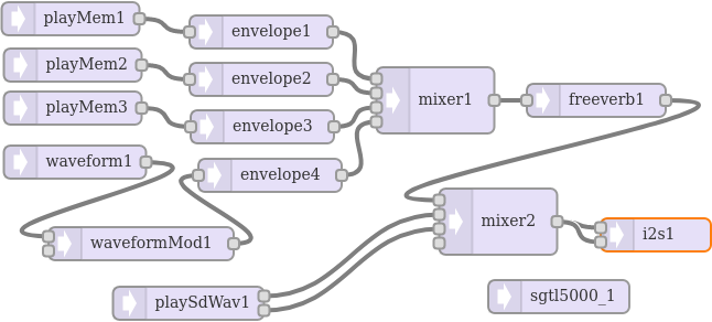
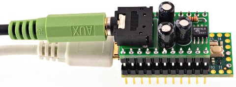
- I2S / TDM
- Most commonly used with the audio shield,
2 digital audio ports can simultaneously transmit and receive up to
8 audio channels using I2S protocol, or up to 16 channels using
TDM.
Alternately, a special format used by inexpensive
PT8211 DAC
chips can be used.
- I2SI - 1 stereo output pin, 1 stereo input pin, 3 stereo input or output pins
- I2S2 - 1 stereo output pin, 1 stereo input pin
- S/PDIF
- The I2S port may be used to receive and transmit S/PDIF. The S/PDIF is independent of both I2S/TDM ports and can be used simultaneously. Either or both of the I2S ports may also be used to transmit S/PDIF.
- Analog Input (ADC)
- 1 analog input pins may be used for audio inputs. Using an ADC pin for audio input currently has only "experimental" software support.
- MQS Output
- This pulsed digital output which blends PWM with oversampling & noise shaping can be used to drive small speakers. Or the output may be low-pass filtered to give analog signals. While called "Medium Quality Sound", the performance is surprisingly good.
Lights & LEDs
- WS2812B / NeoPixel
- Two high performance non-blocking libraries support use of WS2812B LEDs. OctoWS2811 transmits any number of outputs in parallel, allowing almost any number LEDs to be refreshed at up to 30 Hz video rate. On Teensy 4.0, OctoWS2811 supports use of any number of digital pins, not limited to only 8 pins as on Teensy 3.x. WS2812Serial transmits a single output, but up to 8 instances may be used. Non-blocking transmission uses DMA to transmit automatically, while your code is able to continue running. This much more allows complex animations or efficent communication than traditional blocking.
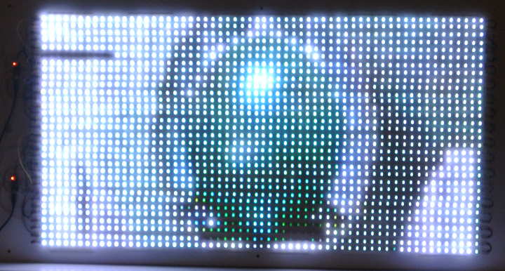
- SmartMatrix & SmartLED Shield for HUB75 RGB LED Panels
- SmartLED Shield (version 5) enables Teensy 4.0 to drive high-quality graphics to large HUB75 RGB LED panel arrays (from 32x16 up to 128x64 pixels). The SmartMatrix library makes it easy to draw basic graphics, create scrolling and static text, draw beautiful patterns using FastLED, and play animated GIFs on the panel. SmartMatrix uses Teensy 4.0's special features to send graphics data with minimal CPU usage, so you can use the processor to do other tasks in parallel such as SPI communication, file decoding, or complex rendering.
- DMX Lighting Control
- Any of the 7 serial ports may be used for efficient communication with DMX lighting controllers.
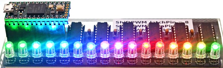
- RGB LEDs
- Ordinary LEDs may be variable-brightness controlled by PWM, or the SoftPWM & ShiftPWM libraries.
Timing
- Crystals & Clock Generation
- Two crystals prodvide accurate timing. A 24 MHz crystal is the basis for the system clock and most peripherals. A phase locked loop (PLL) increases the 24 MHz up to the system clock speed. A separate 32.768 kHz crystal is used for the Real Time Clock (RTC). If a coin cell is added to VBAT, the 32.768 kHz oscillator continues keeping date/time while main power is off.
- Interval Timers
- 4 timers are dedicated to running a function at precisely timed intervals. These are configured using the IntervalTimer class.
- PWM Timers
- 32 timers control PWM pins,
or may be used for other timing functions.
Normally these timers are accessed with analogWrite or libraries, but they
have many very advanced features which may be accessed by direct hardware
register use.
- FlexPWM1 Module0 - Controls PWM pins 1, 36, 37.
- FlexPWM1 Module1 - Controls PWM pins 0, 34, 35.
- FlexPWM1 Module2 - Controls PWM pins 24, 38, 39.
- FlexPWM1 Module3 - Controls PWM pins 7, 8, 25.
- FlexPWM2 Module0 - Controls PWM pins 4, 33.
- FlexPWM2 Module1 - Controls PWM pin 5.
- FlexPWM2 Module2 - Controls PWM pins 6, 9.
- FlexPWM2 Module3 - No pins accessible.
- FlexPWM3 Module0 - No pins accessible.
- FlexPWM3 Module1 - Controls PWM pins 28, 29.
- FlexPWM3 Module2 - No pins accessible.
- FlexPWM3 Module3 - No pins accessible.
- FlexPWM4 Module0 - Controls PWM pin 22.
- FlexPWM4 Module1 - Controls PWM pin 23.
- FlexPWM4 Module2 - Controls PWM pins 2, 3.
- FlexPWM4 Module3 - No pins accessible.
- QuadTimer1 Module0 - Controls PWM pin 10.
- QuadTimer1 Module1 - Controls PWM pin 12.
- QuadTimer1 Module2 - Controls PWM pin 11.
- QuadTimer1 Module3 - No pins accessible.
- QuadTimer2 Module0 - Controls PWM pin 13.
- QuadTimer2 Module1 - No pins accessible.
- QuadTimer2 Module2 - No pins accessible.
- QuadTimer2 Module3 - No pins accessible.
- QuadTimer3 Module0 - Controls PWM pin 19.
- QuadTimer3 Module1 - Controls PWM pin 18.
- QuadTimer3 Module2 - Controls PWM pin 14.
- QuadTimer3 Module3 - Controls PWM pin 15.
- QuadTimer4 Module0 - No pins accessible. Used by OctoWS2811 library, ADC Library
- QuadTimer4 Module1 - No pins accessible. Used by OctoWS2811 library
- QuadTimer4 Module2 - No pins accessible. Used by OctoWS2811 library
- QuadTimer4 Module3 - No pins accessible. Used by Audio for ADC timing, and ADC Library
- Watchdog Timer
- 3 separate watchdog timers are meant to reboot Teensy if your software crashes or gets stuck. Once started, the watchdog timer must be periodically reset. If the software stops resetting the timer for too long, Teensy reboots.
- Special Timers
- These extra timers allow delays, analog sample rate timing, carrier modulation,
and other special timing tasks to be performed, without consuming any of the
normal PWM-oriented timers.
- GPT1 - Generic 32 bit timer
- GPT2 - Generic Generic 32 bit Timer
- Quadrature Encoders - 4 special timers are meant for decoding quadrature signals.
- Cycle Counter
- A 32 bit counter increments every CPU clock cycle (600 MHz). ARM_DWT_CYCCNT may be read by programs to precisely measure short time duration time.
- SysTick
- This system timer generates an interrupt every millisecond. Most of the software timing features use this Systick timer.
- Software Timing
- Many common timing requirements can be met using the software timing features.
- delay(), delayMicroseconds(), delayNanoseconds() - Simple delay for milliseconds, microseconds, or nanoseconds.
- elapsedMillis, elapsedMicros - These C++ classes act as a variable which automatically increments ever millisecond or microsecond. These can be written or modified as needed, which greatly simplifies implementation of repetitive tasks, measuring elapsed time, inactivity timeouts, and so on. The number of these variable is only limited to the available memory.
- millis(), micros() - Stardard Arduino functions for the system time in milliseconds and microseconds.
- Real Time Clock - Date & Time
- The RTC keeps track of date / time. The Time library is typically used together with the RTC. Teensy Loader automatically initializes the RTC to your PC's time while uploading. If a coin cell is connected to VBAT, the RTC will continue keeping time while power is turned off.
Power
- USB Power
- Normally Teensy is powered by your PC or USB hub, through a USB cable. The USB power arrives at the VUSB pin, which is connected VIN and powers the entire board.
- VIN Pin
- When USB power is not used, 5V power may be applied to the VIN pin. Because VIN & VUSB are connected, power should not be applied to VIN while a USB cable is used, to prevent the possibility of power flowing back into your computer. Alternately, a pair of pads on the bottom side may be cut apart, to separate VUSB from VIN, allowing power to be safely applied while USB is in use. (TODO: VUSB-VIN pads photo, right side)
- 3.3V Power
- Teensy 4.0 has a voltage regulator which reduces the 5V VUSB / VIN power to 3.3V for use by the main processor and most other parts. Additional circuitry may be powered from the 3.3V pin. The recommended maximum for external 3.3V usage is 250mA. Teensy 4.0 is not meant to receive power on its 3.3V pin, but this can be done with special modificaton.
- USB Host
- Teensy 4.0 does not have circuitry to manage the power to USB devices (as Teensy 4.1 does). The USB host port is data pins only. When Teensy 4.0 is powered by a USB cable, or a limited 5V power supply, USB devices should not be hot plugged.
- Power Consumption
- When running at 600 MHz, Teensy 4.0 consumes approximately 100 mA current. Reducing CPU speed to 528 MHz or lower reduces power consumption.
- Low Power Features
- Snooze library (TODO: more info here...)
- CPU Voltage Control
- A DC-DC buck converter creates lower voltage needed for the CPU. Software can control this voltage, in 50 mV steps. At 600 MHz, the CPU runs on 1.25V. For 528 MHz and lower, 1.15V is used. At 24 MHz, the CPU runs on only 0.95 volts. When overclocking, higher voltages are automatically used.
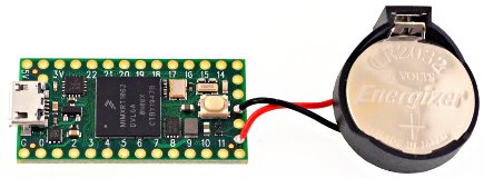
- VBAT
- A 3 volt coin cell may be connected to VBAT & GND to allow the RTC to keep track of date / time while power is off. A CR2032 type battery is recommended, though other 3V coin cells may also be used.
- On / Off Pin and Power Control
- A special low power state which turns off the 3.3V power can be controlled by the On/Off pin. A pushbutton is meant to be connected between On/Off and GND. While running, holding the button for 4 seconds turns off power. Pressing for 0.5 seconds while power is off turns the 3.3V power back on and reboots the processor. If a coin cell is connected to BVAT, the power state is retained when main power is disconnected. Without VBAT, the power state always defaults to 3.3V power on, even if the On/Off button had been used to turn off 3.3V before main VIN/VUSB power was removed.
Memory
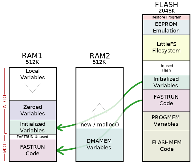
- Program / Flash Memory
- Teensy 4.0 has 2 Mbyte of flash memory intended for storing your code. The flash memory can also store read-only variables and arrays. A portion of the flash memory may be used for file storage using the LittleFS library. The top 64K of this memory is reserved for EEPROM emulation data and the LED blink restore program.
- RAM
- 1024K of memory is available for variables and data. Half of this memory (RAM1) is accessed as tightly coupled memory for maximum performance. The other half (RAM2) is optimized for access by DMA. Normally large arrays & data buffers are placed in RAM2, to save the ultra-fast RAM1 for normal variables.
- EEPROM
- 1080 bytes of emulated EEPROM memory is supported. Writing to this memory temporarily stalls code execution from flash. The EEPROM library is typically used to access this memory. AVR libc functions may also be used.
- Static Allocation Keywords
- When the compiler builds your program, all global variables, static variables,
and compiled code is assigned to dedicated locations in memory. This is called
static allocation, because the memory addresses are fixed. By default, allocation
tries to use the ultra-fast DTCM & ITCM memory. The following keywords allow
control over where the compiler will place your variables and code within the memory.
- DMAMEM - Variables defined with DMAMEM are placed at the beginning of RAM2. Normally buffers and large arrays are placed here. These variables can not be initialized, your program must write their initial values, if needed.
- PROGMEM & F() - Variables defined with PROGMEM, and strings surrounded by F() are placed only in the flash memory. They can be accessed normally, special functions normally used on 8 bit boards are not required to read PROGMEM variables.
- FASTRUN - Functions defined with "FASTRUN" are allocated in the beginning of RAM1. A copy is also stored in Flash and copied to RAM1 at startup. These functions are accessed by the Cortex-M7 ITCM bus, for the fastest possible performance. By default, functions without any memory type defined are treated as FASTRUN. A small amount of memory is typically unused, because the ITCM bus must access a memory region which is a multiple of 32K.
- FLASHMEM - Functions defined with "FLASHMEM" executed directly from Flash. If the Cortex-M7 cache is not already holding a copy of the function, a delay results while the Flash memory is read into the M7's cache. FLASHMEM should be used on startup code and other functions where speed is not important.
- Dynamic Allocation
- As your program runs, it may use all of the RAM which was not reserved by
static allocation. Because the specific memory address for each variable is
computed as your program runs, this is called dynamic memory allocation.
- Local Variables - Local variables, and also return addresses from function calls and the saved state from interrupts are placed on a stack which starts from the top of RAM1 and grown downward. The amount of space for local variable is the portion of RAM1 not used by FASTRUN code and the initialized and zeroed variables.
- Heap - Memory allocated by C++ "new" and C malloc(), and Arduino String variables are placed in RAM2, starting immediately after the DMAMEM variables.
- RTC RAM
- 16 bytes of memory are located within the RTC. If a coin cell is connected to VBAT, contents of this memory is preserved while power is off. This memory is accessed as 32 bit registers LPGPR0-LPGPR3.
- SD Card
- 8 small pads on the bottom of Teensy 4.0 provide the same signals as the built in SD socket of Teensy 4.1. These pads are meant to fit connector HFW8R-1STE1H1LF. The Arduino SD library is used to access the card, using SD.begin(BUILTIN_SDCARD). This built in SD socket uses fast 4 bit native SDIO to access the card. SD cards may also be used via the SPI pins, with SD.begin(cspin), using the slower single bit SPI protocol to access the card.
- SPI Flash
- Flash memory chips may be added using the SPI pins. These are supported by the SerialFlash and LittleFS libraries.
Programming
- Teensy Loader
- Programming of Teensy's flash memory is done by the Teensy Loader application. Normally the Arduino IDE or other software is used to compose code, and it automatically runs Teensy Loader as needed. If you have compiled code in HEX file format, Teensy Loader can be used stand-alone to write your HEX file into Teensy's flash memory.
- Automatic Software Entry to Program Mode
- While developing with Teensy, loading normally happens automatically after compiling your program. A "teensy_reboot" utility looks for your Teensy on all USB ports and sends a request (serial baud rate or HID feature report) to automatically switch to programming mode.
- Program Pushbutton / Pin
- If code previously written to Teensy is not listening for USB communication, automatic entry to programming mode is not possible. A physical pushbutton is provided to allow recovery from bad code. Pressing the button button puts Teensy into programming mode. It is not a "reset button" which restarts your program. The button is dedicated to recovery from bad code. A Program pin also allows external hardware to force entry to programming mode.
- Red LED: Bootloader Active & Flash Writing
- A red LED is dedicated to showing the bootloader status. When the bootloader is active but waiting for PC communication, this red LED is dim. While actually writing to the flash memory, it is on bright.
- Reset
- Teensy 4.0 does not have a hardware reset signal available. Reset can be accomplished under software control using the watchdog timers or SCB_AIRCR register.
- Memory Wipe & LED Blink Restore
- Teensy 4.0 will fully erase its non-volatile memory and return the flash memory to a simple LED blink program if the program button is held between 13 to 17 seconds. The red LED flashes briefly at the beginning of this time window. During flash erase, the red LED is on bright. When completed, Teensy 4.0 will automatically reboot and run the LED blink program, causing the orange LED to blink slowly.
- Bootloader Chip
- Teensy 4.0's bootloader is stored in a dedicated chip. All of the main chip's memory is available to your program. Upon power up, your program runs immediately. The bootloader does not run automatically at startup, as is done with most Arduino compatible boards. The physically separate chip keeps Teensy's bootloader separate from your code and prevents flash programming from being able to damage or erase the bootloader.
Code Security
- Secure Firmware Update
- When locked, Teensy 4.0 can be reprogrammed using encrypted EHEX files. EHEX files may be published to allow anyone to securely update firmware. Your private key is needed only to create the EHEX file, which then may be loaded onto the hardware by people without access to your key. Once locked, Teensy can only be programmed by EHEX files created using your key.
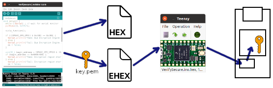
- Program Memory Protection
- Code security protects your program code from unauthorized access and coping. When compiling, your program is encrypted. When run, the IMXRT Bus Encryption Engine provides on-the-fly decryption as your program executes. If an attacker removes and reads the flash memory chip from Teensy 4.1, or attempt to capture the USB communication from Teensy Loader, or copies the EHEX file Teensy Loader opens, they get only an encrypted copy of your program.
- Secure Firmware Update
- Users can be given an EHEX file and Teensy Loader to securely update commercial products or secure applications which embed a Lockable Teensy, without gaining access to the original program code. Of course the key already in its fuse memory and secure mode locked when the product is shipped.
- Permanent Secure Mode
- Brand new Teensy 4.1 can only run unencrypted programs. Once a key is written into fuse memory, either encrypted or unencrypted programs can run. Secure mode permanently disables the ability to run unencrypted code, and activates hardware security features.
- Lockable Teensy
- Secure mode can only be activated on Lockable Teensy. While Standard and Lockable Teensy are identical hardware, the permanent fuse configuation differs. Standard Teensy does not allow changes to fuses affecting boot or other critical configuration. Standard Teensy is meant to safe from "bricking" by programs which could write to fuse memory, but this safety means secure mode can not be activated. Standard Teensy can have a key written and can run encrypted code, but encryption alone is not fully secure. Only Lockable Teensy provides proper code security, and only when a key is written and secure mode is locked.
- Authentication
- The encryption process includes digital signature authentication. In secure mode, this signature is checked before any code can be decrypted.
- JTAG Disable
- Secure mode permanently disables the JTAG port. To enter programming mode without JTAG, Teensy Loader and the EHEX file automatically utilize a loader utility which is authenticated by your key's digitial signature, and in turn uses secure hash checks to fully authenticate all components of the programming process.
- EHEX File Format
- Teensyduino packages your encrypted code, metadata, a startup shim, loader utility, digital signatures and other essential details into a single EHEX file. This EHEX may be given to customers or untrusted parties to perform code updates with the convenice of a single file. The EHEX format and encryption details are documented on the code security page
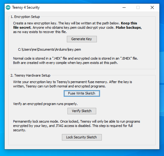
- Key Management
- To make creating and using your key simple, Teensyduino adds a "Teensy 4 Security" window to the Arduino Tools menu. These functions can also be accessed from a command line utility for use from non-Arduino tools or automated scripts.
Special Features
- Nested Interrupt Controller
- Priority nesting allows low latency for critical interrupts while lower priority interrupts are in use. Teensyduino's libraries utilize interrupt nesting with priority level defaults which allow many types of libraries to work well when used together.
- Direct Memory Access (DMA)
- Teensy 4.0 has a general purpose 32 channel DMA controller. Optimized Audio, LED and display libraries make uses of these DMA channels. A DMAChannel.h abstraction layer is provided. The USB device, USB host, SD card and Ethernet peripherals also have specialized DMA engines built in.
- Random Number Generator
- True random number hardware is capable of generating random data at (TBD) rate. The Entropy library is used to access the random number generator.
- Cryptographic Acceleration
- Symetric ciphers and one-way hash can be computed by hardware, but currently no library support exists to utilize this hardware.
- Temperature Sensor
- A built in temperature sensor allows reading the temperature inside the main chip. The InternalTemperature library can be used to access this sensor.
Technical Information
- IMXRT1060 Manual - All the useful peripheral programing info (with annotations for Teensy)
- IMXRT1060 Datasheet - Only the electrical specifications
- IMXRT1060 Errata Rev B - Applies to Teensy 4.0 after December 2021
- IMXRT1060 Errata Rev A - Applies to Teensy 4.0 before December 2021
- W25Q16JV-DTR Datasheet - Flash memory chip
- ARM Cortex-M7 Reference Manual
- ARM v7-M Architecture Reference Manual - ARM Processor low-level details - free, but difficult to read
- Definitive Guide to ARM Cortex-M3 & Cortex-M4 (book) - ARM Processor low-level details - easier to read
Dimensions
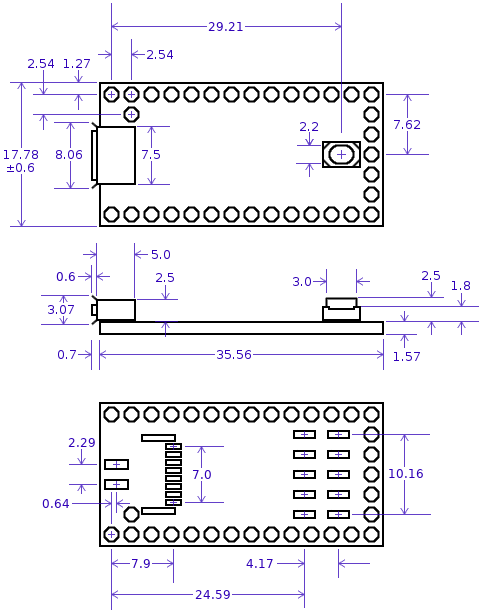
Bottom pad sizes: USB Host: 3.048x1.016, SD: 2.000x0.600, Pins 24-33: 2.794x0.889.
Finished hole diameter is 0.965mm (34 locations).
User contributed 3D CAD models may be available on the forum.
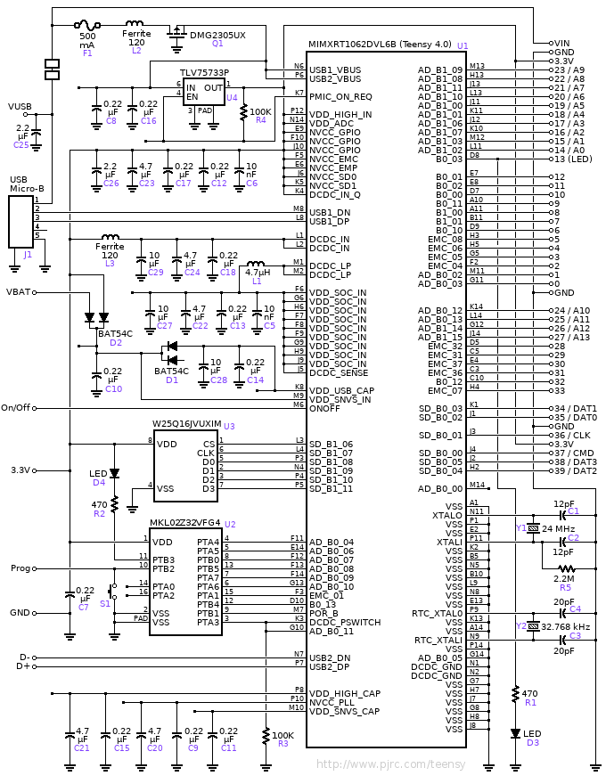
Schematic
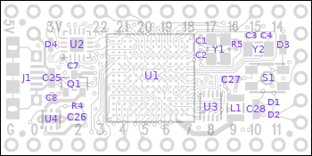
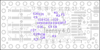
Component Locations
Design Changes
Teensy 4.0 manufactured after December 2021 has U1 part number MIMXRT1062DVL6B. Prior boards had the older version ending with "A". The "B" version fixes obscure hardware bugs with CAN bus and USB device isochronous mode.Teensy 4.0 manufactured after March 2022 has U4 replaced by AP7366, and BAT54C (D1,D2) replaced by BAS40-05V.
Teensy 4.0 manufactured after June 2022 has U2 replaced by GD32E230F8.
Teensy 4.0 manufactured after August 2022 has R4 changed to 470K, which helps with startup with VUSB-VIN is lower than 4.1V.
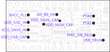
Test Points
Regulatory Compliance
For Teensy 4.0 manufactured and sold by SparkFun Electronics, after March 2025:- FCC and ISED Compliance, Teensy 4.0
- FCC and ISED Compliance, Teensy 4.0 lockable
- FCC and ISED Compliance, Teensy 4.0 with pins
- CE and UKCA Compliance, Teensy 4.0
- CE and UKCA Compliance, Teensy 4.0 lockable
- CE and UKCA Compliance, Teensy 4.0 with pins
- USA Section 889 Statement
- RoHS and REACH compliance is within each CE-UKCA declaration of conformity