Audio Adaptor Boards for Teensy
SparkFun is now manufacturing Teensy products. You can buy directly at SparkFun.

|
TEENSY4_AUDIO | Audio board for use with Teensy 4.0 - 4.1, (Rev D) |
This audio adaptor lets you easily add high quality 16 bit, 44.1 kHz sample rate (CD quality) audio to your projects with Teensy 3.0, 3.1, 3.2, 3.5, 3.6 (Rev C), or 4.0, 4.1 (Rev D, D2). The older versions can be used with Teensy 4.0 by wires or an adaptor PCB.
All versions of the audio shield support stereo headphone and stereo line-level output, and also stereo line-level input or mono microphone input.
The Teensy Audio Library lets you use the input and output simultaneously together with a toolkit of audio processing objects, to easily create all types of sophisticated audio applications. You can play multiple sound files, create synthesized waveforms, apply effects, mix multiple streams and output high quality audio to the headphones or line out pins.
Teensy 3.x have the Cortex-M4 DSP instructions which provide plenty of computational power for real-time FFT (spectrum analysis), opening up the possibility of creating advanced sound-reactive projects. Teensy 4.x with Cortex-M7 provides even more DSP capability, allowing sophisticated synthesis applications to create many simultaneous "voices" or effects.
Two of these 14x1 pins can be used to easily
soolder the Teensy 3.x and audio board together.
A 14 pin socket and 14 pin header can be used to make them plug together.
An optional Thumbwheel Potentiometer can be added for volume or control an audio parameter.
| Function | Teensy 4.x Pins Rev D, D2 | Teensy 3.x Pins Rev C | Shareable |
|---|---|---|---|
| Audio Data | 7, 8, 20, 21, 23 | 9, 11, 13, 22, 23 | |
| Audio Control | 18, 19 | 18, 19 | SDA, SCL (other I2C chips) |
| Volume Pot | 15 (A1) | 15 (A1) | - |
| SD Card | 10, 11, 12, 13 | 7, 10, 12, 14 | MOSI, MISO, SCK (other SPI chips) |
| Memory Chip | 6, 11, 12, 13 | 6, 7, 12, 14 | MOSI, MISO, SCK (other SPI chips) |
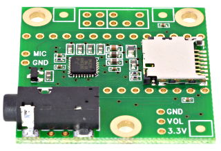
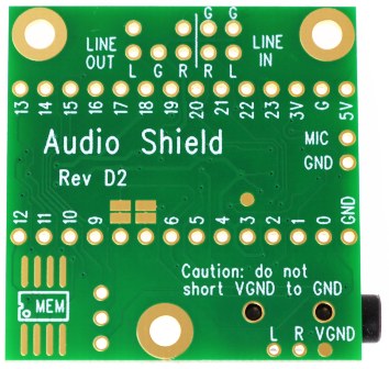
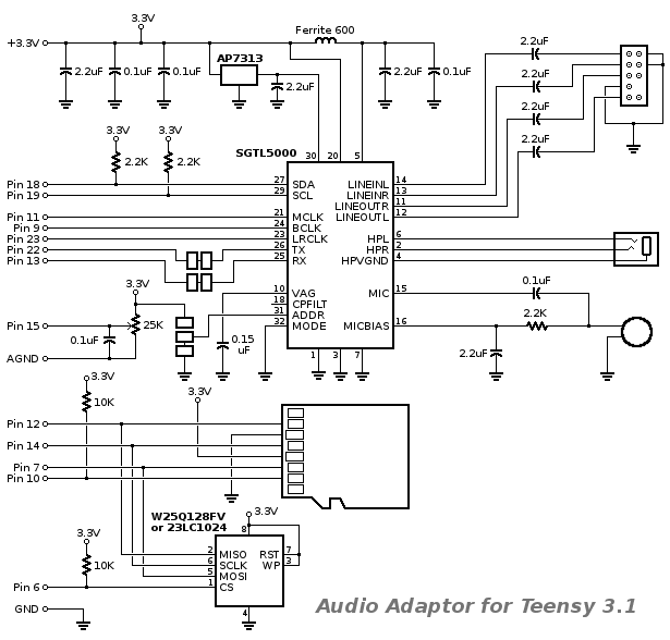
| Front Side Rev D2 (for Teensy 4.x) | Front Side Rev D (for Teensy 4.x) | Front Side Rev C (for Teensy 3.x) |
|---|---|---|
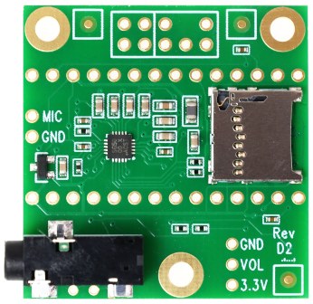 | 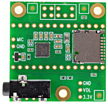 | 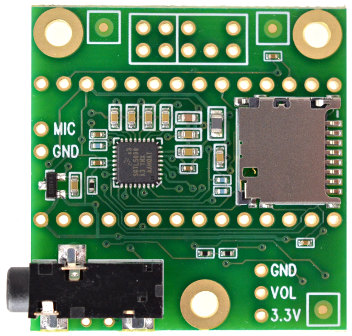 |
| Back Side Rev D2 (for Teensy 4.x) | Back Side Rev D (for Teensy 4.x) | Back Side Rev C (for Teensy 3.x) |
 | 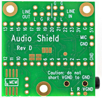 |  |
Mechanical drawing and Eagle library.
Estimated power consumption.
3D CAD models.
Optional Add-Ons
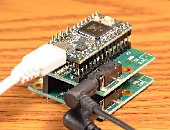
This photo shows a Teensy 3.1 soldered under the audio adaptor using two 14x1 pins.
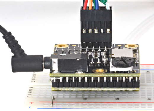
The optional volume knob and line in/out header are also added.
Signals to Teensy
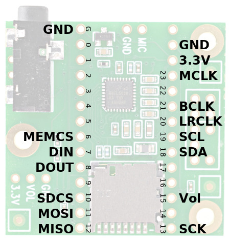
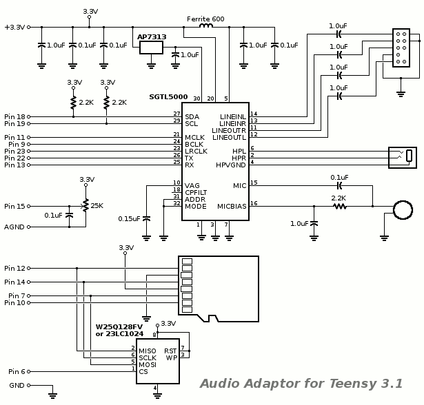
The audio chip, part number SGTL5000, connects to Teensy using 7 signals. The I2C pins SDA and SCL are used to control the chip and adjust parameters. Audio data uses I2S signals, DIN (which the audio shield uses to make analog signals at the headphones and line out) and DOUT (which the audio shield creates from reading the analog signals at line in or microphone), and 3 clocks, LRCLK (44.1 kHz), BCLK (1.41 or 2.82 MHz) and MCLK (11.29 MHz). All 3 clocks are created by Teensy. Most I2S software on Teensy uses 64 bits per LRCLK (BCLK=2.82 MHz), where the upper 16 bit of each 32 bit word are used and the lower 16 bits are ignored. However, some I2S support uses only 32 bits per LRCLK (BCLK=1.41 MHz). Refer to the Design Tool documentation for each I2S input or output for details. The SGTL5000 listens for clocks. All its clock pins are inputs.5 additional signals can optionally connect memory to store sounds and 1 optional analog signal can connect a thumbwheel pot to allow software which reads the signal with analogRead() and use the readings to control any audio parameter, such as volume. While labeled "Vol" and most commonly used to control volume, the actual purpose of this analog pin is controlled by software written to Teensy.
| Rev D, D2 (Teensy 4.0) | Rev C (Teensy 3.x) |
|---|---|
 | 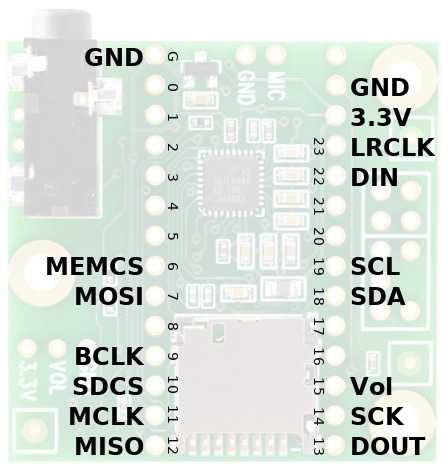 |
| Audio Shield Signal | Rev D, D2 (Teensy 4.x) | Rev C (Teensy 3.x) | Required For | Function |
|---|---|---|---|---|
| MCLK | 23 (MCLK1) | 11 (MCLK) | Audio | Audio Master Clock, 11.29 MHz |
| BCLK | 21 (BCLK1) | 9 (BCLK) | Audio | Audio Bit Clock, 1.41 or 2.82 MHz |
| LRCLK | 20 (LRCLK1) | 23 (LRCLK) | Audio | Audio Left/Right Clock, 44.1 kHz |
| DIN | 7 (OUT1A) | 22 (OUT) | Audio Output | Audio Data from Teensy to Audio Shield Goes to both headphone jack and Line-Out pins |
| DOUT | 8 (IN1) | 13 (IN) | Audio Input | Audio Data from Audio Shield to Teensy Comes from either Microphone or Line-In pins |
| SCL | 19 | 19 | Audio Config | Control Clock (I2C) |
| SDA | 18 | 18 | Audio Config | Control Data (I2C) |
| SCK | 13 | 14 | Optional Data SD or MEM | Data Storage (SPI) Clock |
| MISO | 12 | 12 | Optional Data SD or MEM | Data Storage (SPI) from SD/MEM to Teensy |
| MOSI | 11 | 7 | Optional Data SD or MEM | Data Storage (SPI) from Teensy to SD/MEM |
| SDCS | 10 | 10 | Optional Data SD Card | Chip Select (SPI) for SD Card |
| MEMCS | 6 | 6 | Optional Data MEM Chip | Chip Select (SPI) for Memory Chip |
| Vol | 15 / A1 | 15 / A1 | Optional Knob | Volume Thumbwheel (analog signal) |
The SD socket is accessed with 4 SPI pins. For Rev C used with Teensy 3.2, 3.5, 3.6, SCLK and MOSI are used at alternate locations. See the audio library examples for details on how to select these different pins. The SD card is useful for playing music. Sandisk and other good quality SD cards are capable of playing 2 WAV files simultaneously.
Wires for MCLK, BCLK, LRCLK, TX & RX should be kept short. The audio shield is meant to connect to Teensy through short pins. Wires can be used, but wires must be short to avoid problems.
The line in/out header uses a pinout compatible with the AC97 audio header on PC motherboards. The front panel cables from most PCs can be connected, or wires can be soldered directly to the pins.
Schematic, Rev D2
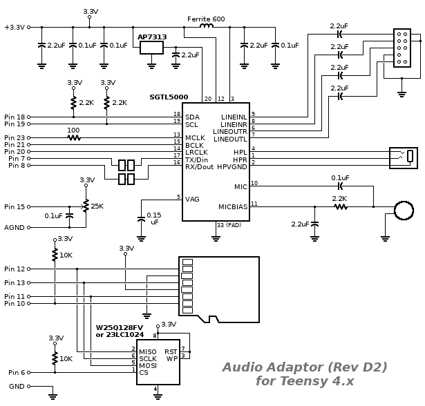
In January 2023, Rev D2 was created due to shortages on the 32 pin version of SGTL5000 and the original SD socket. Rev D2 is functionally the same as Rev D, except the the I2C address selection pads. The I2C address is not configurable on the 20 pin SGTL5000 chip.
Schematic, Rev D
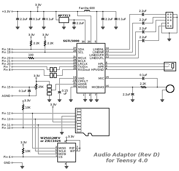
In September 2019, Rev D was created for Teensy 4.0. The circuitry is the same as Rev C, but the I2S digital audio signals and SPI signals for the SD card are routed to the pins Teensy 4.0 uses.
Forum user bmo created a Kicad Symbol and Footprint for the Rev D Audio Shield.
Schematic, Rev C

In early 2019, a 100 ohm resistor was added to the MCLK signal.
Schematic, Rev B
In January 2015, small improvements were added. The 1.0 µF capacitors were increased to 2.2 µF, to improve performance for sub-audible and extremely deep base sounds. 10K pullup resistors were added to pins 6 and 10.
Solder pads were added to the I2S transmit and receive lines, and the I2C
address configuration pin. Teensy 3.1 & 3.2 are
theoretically capable of quad channel I2S audio. These pads are intended to allow a
second audio board to be used, for 4 channel audio input and output! (TODO: 4 channel support has not yet been tested with Teensy 3.5 or 3.6)
Update: the Teensy Audio Library now supports quad channel output. For details, see File > Examples > Audio > HardwareTesting > SGTL5000 > QuadChannelOutput.
Sparkfun has great wiring instructions for 4 channel audio.
Schematic, Rev A
Optional Memory Chip(s)
A W25Q128JV or W25Q128FV flash memory chip may be added on the bottom side. The Teensy Audio Library can play audio clips from this memory, using the SerialFlash library. This flash memory has much lower access latency than SD cards, which allows many sounds to be played simultaneously.Future versions of the audio library may also use this low latency flash memory for wavetable synthesis.
Alteratively, a 23LC1024 RAM memory chip may be added. The Teensy Audio Library can use the RAM chip for a multi-tap delay line, up to 1.5 seconds. See this demo video for details.
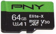
Recommended SD Card
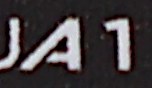
Most SD cards are optimized for sequential access, where a camera or camcorder reads or writes a single large file. All SD cards work well for playing a single WAV file at a time.Cards with "A1" or "A2" rating are likely to have better performance for use with Teensy.
Since Teensyduino 1.54, the SD library supports up to 2 TB size. Teensyduino 1.53 and earlier only supported cards up to 32GB size.
Very old cards smaller than 8GB may have trouble with the built in SD socket on Teensy 3.5, 3.6, 4.1, but usually with fine with the SPI-based socket on the audio shield.
The audio library includes a simple benchmark to test SD cards. Open it from File > Examples > Audio > HardwareTesting > SdCardTest.