Teensy 3.2 - 4.1 OctoWS2811 Adaptor
SparkFun is now manufacturing Teensy products. You can buy directly at SparkFun.

|
OCTO28_ADAPTOR | OctoWS2811 Adaptor for Teensy 3.2 - 4.1 |
Recommended Accessories:
Using Teensy 3.2 or 4.0:
Sockets 14x1 (2),
Pins 14x1 (2)
Using Teensy 3.5 or 3.6 or 4.1:
Sockets 14x1 (2),
Pins 14x1-D (2)
 with Teensy 3.2 - 4.1 |
|
(per Teesny) What limits the number of LEDs can you use with each Teensy? 1872: Teensy 3.0's RAM limit (90% used)
4416: 60 HZ refresh 6000: 120V USA power* 8800: 30 Hz refresh (uses 86% of Teensy 3.2's available RAM)
10920: Limit due to DMA hardware, 1365 LEDs per pin, using 8 pins To connect more LEDs, use multiple Teensy and OctoWS2811 Adaptors with their SYNC signals tied together. * - Approximate, based on typical power supply efficiency and standard 15 amp circuit breakers |
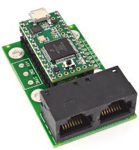
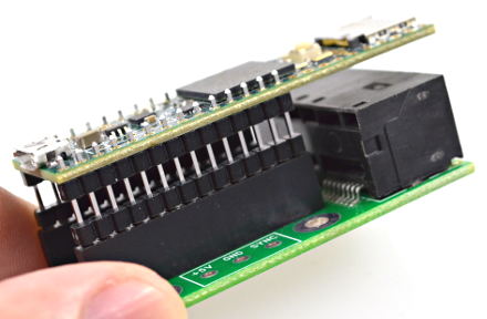
This adaptor board connects Teensy 3.2 - Teensy 4.1 to thousands of LEDs using the OctoWS2811 Library.
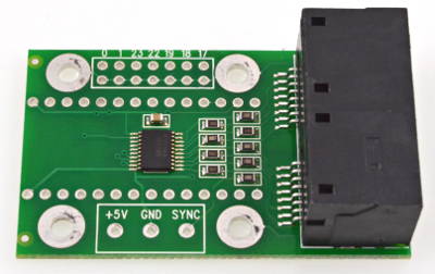
The adaptor features a 74HCT245 buffer chip and 100 ohm impedance matching resistors. CAT6 Ethernet cable is used from this board to the LED strips. CAT6 cable is designed for very high bandwidth, minimal cross-talk between twisted pairs, and 100 ohm impedance, for a very high quality signal. The RJ-45 network jacks allow your LED array to be easily disconnected from the electronics.
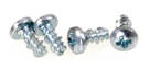
Four self-threading screws are supplied with the OctoWS2811 Adaptor board.
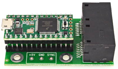
Teensy 3.x is added on top of the adaptor using stacking header pins, or a header and socket pair if you wish to be able to remove the Teensy 3.x board.
Teensy 3.2, Pins,
and CableGaurd 500 enclosure are sold separately. Four screws are included.
This adaptor can also be used with the larger Teensy 3.5, 3.6, 4.1 boards using double insulator pins and sockets. Together, these are tall enough to allow the longer board with SD socket to overhang the RJ-45 connectors.
Teensy 3.6, Pins,
sockets,
and CableGaurd 500 enclosure are sold separately. Four screws are included.
This adaptor board is designed to fit inside a CableGaurd 500 Coax Demarcation Enclosure (not sold by PJRC). The CG-500 is a very durable enclosure meant for outdoor applications. The outside size is approximately 6.5 by 8 inches (16.5 by 20.3 cm). Even though this is the smallest CableGaurd enclosure, there's plenty of room inside for even two OctoWS2811 adaptors.
The included self-threading screws fit the mounting posts on the CG-500 enclosure.
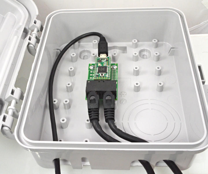
The eight LED outputs are sent on two CAT6 Ethernet cables.
Signals with CAT6 T568B Termination:
(most CAT6 cables sold in the USA are this type)
| Top RJ-45 Jack | Bottom RJ-45 Jack | |||
|---|---|---|---|---|
| Wire | Signal | Wire | Signal | |
| Orange | LED Strip #1 Data | Orange | LED Strip #5 Data | |
| White/Orange | LED Strip #1 Ground | White/Orange | LED Strip #5 Ground | |
| Blue | LED Strip #2 Data | Blue | LED Strip #6 Data | |
| White/Blue | LED Strip #2 Ground | White/Blue | LED Strip #6 Ground | |
| Green | LED Strip #3 Data | Green | LED Strip #7 Data | |
| White/Green | LED Strip #3 Ground | White/Green | LED Strip #7 Ground | |
| Brown | LED Strip #4 Data | Brown | LED Strip #8 Data | |
| White/Brown | LED Strip #4 Ground | White/Brown | LED Strip #8 Ground | |
Signals with CAT6 T568A Termination:
| Top RJ-45 Jack | Bottom RJ-45 Jack | |||
|---|---|---|---|---|
| Wire | Signal | Wire | Signal | |
| Green | LED Strip #1 Data | Green | LED Strip #5 Data | |
| White/Green | LED Strip #1 Ground | White/Green | LED Strip #5 Ground | |
| Blue | LED Strip #2 Data | Blue | LED Strip #6 Data | |
| White/Blue | LED Strip #2 Ground | White/Blue | LED Strip #6 Ground | |
| Orange | LED Strip #3 Data | Orange | LED Strip #7 Data | |
| White/Orange | LED Strip #3 Ground | White/Orange | LED Strip #7 Ground | |
| Brown | LED Strip #4 Data | Brown | LED Strip #8 Data | |
| White/Brown | LED Strip #4 Ground | White/Brown | LED Strip #8 Ground | |
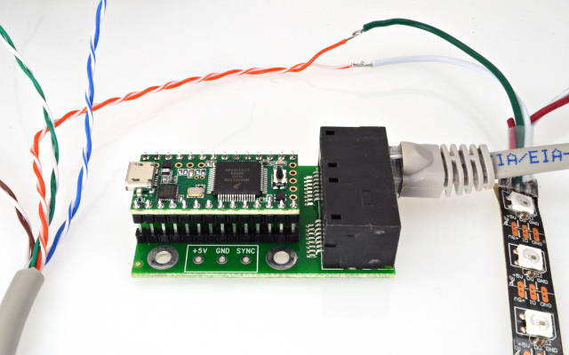
To prepare the data cables, simply cut a CAT6 Ethernet cable in half and carefully strip away the outer jacket to expose long enough sections of the twisted pairs to reach all of your LED strips. Each twisted pair feeds the data input and ground of a single strip.
For best results, the LED power supply ground and Teensy signal ground should meet at or near the LED strip signal inputs. The LED power supplies should be located at close as possible to the LED strips and connected with large diameter wires, to minimize voltage loss due to high current flow.
Do not underestimate the wire sizes needed to deliver power to your LEDs. The most common problem in large LED projects is inadequate power wiring, usually causing flickering or wrong colors.
If Teensy 3.2 will be powered by the LED strip power supply, 5V and ground wires should be run together with the CAT6 cables and connected to the +5V and GND pads on the adaptor boards. The 5.08 mm spacing terminal block may be soldered to the adaptor board, or the wires can be soldered directly. Of course, the VIN-VUSB pads on Teensy 3.2 should be cut apart if Teensy 3.2 receives external power, to avoid feeding the LED power back into your computer.
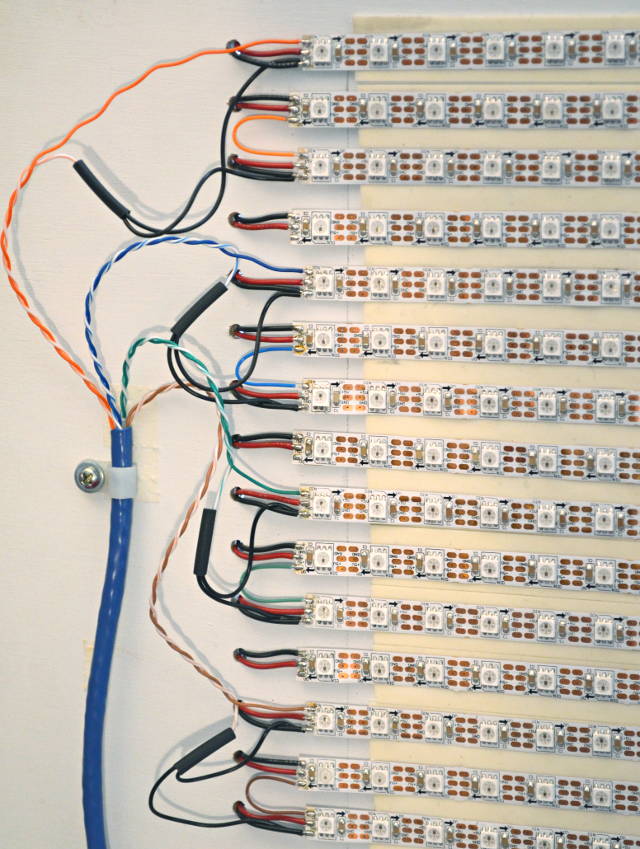
In this example, each OctoWS2811 signal feeds 4 LED strips in back-and-forth rows. The power supplies are mounted to the back side of the display with short, #22 wires feeding power to each LED strip of 60 LEDs.
Short, heavy wires for power, with signal and power grounds meeting at the LED strips provides the highest quality signals without signal interference due to the voltage loss along the power ground lines. Together with the OctoWS2811 adaptor's 5V buffer chip and accurate 100 ohm impedance matching to quality CAT6 cable, this wiring style gives a LED project the best quality signal and power delivery.
TODO: signal quality tests with different length CAT6 cables....
Possible use with APA102 LEDs
It may be possible to use this board with FastLED to drive a long strip of APA102 LEDs, by configuring for SPI output on pins 7 and 14.
Details here:
https://plus.google.com/104301636682478764269/posts/ibHn1CzM6x2
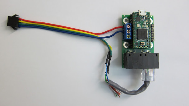
Photo by Steve Caress
Sync Signal
The sync signal allows 2 or 3 boards to tightly synchronize their LED update times, when fed by USB communication which may have slightly different delays or latency to each board.Because this signal is simply connected to a Teensy pin through a 100 ohm resistor, a maximum of 3 boards may be used. To syncrhonize more boards, the master board would need a buffer (or multiple buffers) to transmit the sync signal to all of the other synchronized boards.
Alternately, the PC-side software can be modified to treat all boards as masters, so no SYNC connection is needed between them. On fast computers with good quality (Multi-TT) USB hubs, the USB latency should be very small, so you may not need to use the SYNC signal.