Encoder Library
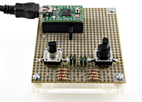
Encoder counts pulses from quadrature encoded signals, which are commonly available from rotary knobs, motor or shaft sensors and other position sensors.
| Download: |
Included with the Teensyduino Installer Latest Developments on Github |
Encoder provides 4X counting mode and highly optimized code (explained below) when running on Teensy or Arduino boards. Chipkit boards have limited support.
Update: TLB has posted code to use Teensy 3.1's hardware quadrature encoders.
Hardware Requirements
 |
Encoders have 2 signals, which must be connected to 2 pins. There are three options.
- Best Performance: Both signals connect to interrupt pins.
- Good Performance: First signal connects to an interrupt pin, second to a non-interrupt pin.
- Low Performance: Both signals connect to non-interrupt pins, details below.
| Board | Interrupt Pins | LED Pin (do not use) |
|---|---|---|
| Teensy 4.0 - 4.1 | All Digital Pins | 13 |
| Teensy 3.0 - 3.6 | All Digital Pins | 13 |
| Teensy LC | 2 - 12, 14, 15, 20 - 23 | 13 |
| Teensy 2.0 | 5, 6, 7, 8 | 11 |
| Teensy 1.0 | 0, 1, 2, 3, 4, 6, 7, 16 | |
| Teensy++ 2.0 | 0, 1, 2, 3, 18, 19, 36, 37 | 6 |
| Teensy++ 1.0 | 0, 1, 2, 3, 18, 19, 36, 37 | |
| Arduino Due | All Digital Pins | 13 |
| Arduino Uno | 2, 3 | 13 |
| Arduino Leonardo | 0, 1, 2, 3 | 13 |
| Arduino Mega | 2, 3, 18, 19, 20, 21 | 13 |
| Sanguino | 2, 10, 11 | 0 |
Low cost encoders only connect their pins to ground. Encoder will activate the on-chip pullup resistors. If you connect lengthy wires, adding 1K pullup resistors may provide a better signal.
Basic Usage
Encoder myEnc(pin1, pin2);Create an Encoder object, using 2 pins. You may create mulitple Encoder objects, where each uses its own 2 pins. The first pin should be capable of interrupts. If both pins have interrupt capability, both will be used for best performance. Encoder will also work in low performance polling mode if neither pin has interrupts.
myEnc.read();Returns the accumulated position. This number can be positive or negative.
myEnc.write(newPosition);Set the accumulated position to a new number.
Understanding Quadrature Encoded Signals
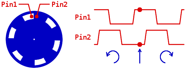
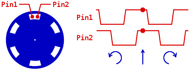
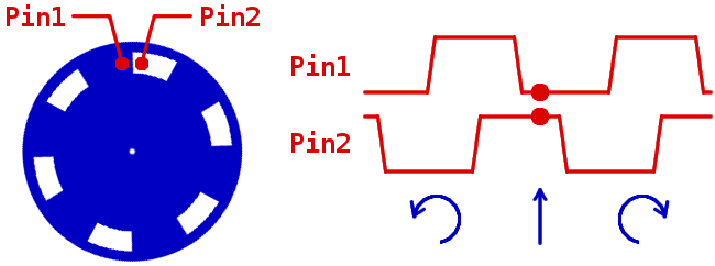
Encoders can sense movement in either direction, by detecting holes or marks as they move past 2 positions. When the blue disc in the diagram below spins clockwise, the changes are first detected by pin 1, and then by pin 2. When it spins counterclockwise, pin 2 is first to detect changes. This scheme is called "quadrature encoding" because the waveforms detected by the 2 pins are 90 degrees out of phase.
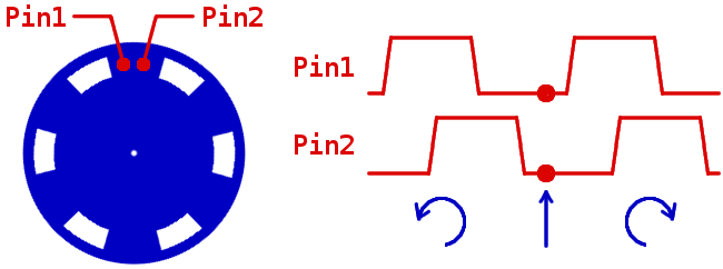 |
The Encoder library monitors the 2 pins and updates a count of the relative change in position. The library updates its count at each change, which is often called 4X counting, since 4 counts are available for each physical mark or hole in the encoder hardware.
Example Program
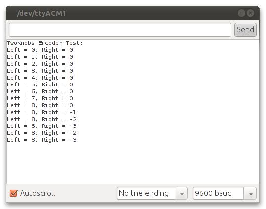
This examples program is available from the menu: File > Examples > Encoder > TwoKnobs./* Encoder Library - TwoKnobs Example * http://www.pjrc.com/teensy/td_libs_Encoder.html * * This example code is in the public domain. */ #include <Encoder.h> // Change these pin numbers to the pins connected to your encoder. // Best Performance: both pins have interrupt capability // Good Performance: only the first pin has interrupt capability // Low Performance: neither pin has interrupt capability Encoder knobLeft(5, 6); Encoder knobRight(7, 8); // avoid using pins with LEDs attached void setup() { Serial.begin(9600); Serial.println("TwoKnobs Encoder Test:"); } long positionLeft = -999; long positionRight = -999; void loop() { long newLeft, newRight; newLeft = knobLeft.read(); newRight = knobRight.read(); if (newLeft != positionLeft || newRight != positionRight) { Serial.print("Left = "); Serial.print(newLeft); Serial.print(", Right = "); Serial.print(newRight); Serial.println(); positionLeft = newLeft; positionRight = newRight; } // if a character is sent from the serial monitor, // reset both back to zero. if (Serial.available()) { Serial.read(); Serial.println("Reset both knobs to zero"); knobLeft.write(0); knobRight.write(0); } }
 |
Interrupt Latency Requirements
Encoder requires low latency response to changes of the signals. Using either the first or both pins with interrupts works very well. However, if interrupts are disabled for lengthy times, either by your code or another library, Encoder may miss a change. The result is incorrect counting. The next 1, 2 or 3 changes may produce wrong results.SoftwareSerial and NewSoftSerial are very likely to cause problems.
Optimized Interrupt Option
When used on Teensy and Arduino, Encoder uses very optimized interrupt routines written in assembly language. Normally, Encoder uses attachInterrupt(), which allows dynamically attaching functions to each interrupt. The dynamic function call adds slight overhead. To eliminate this extra overhead, you can use this option.
// This optional setting causes Encoder to use more optimized code,
// It must be defined before Encoder.h is included.
#define ENCODER_OPTIMIZE_INTERRUPTS
#include <Encoder.h>
Encoder will directly define interrupts the minimum overhead. The downside is a conflict if any other code in your sketch or any libraries you use require attachInterrupt().
Maximum Speed and CPU Usage
SpeedTest example, in File > Examples > Encoder > SpeedTest, provides a simple way to verify how much CPU time Encoder is consuming. The following SpeedTest results have been measured:
| Board | Maximum Interrupt Rate (approximate) | Conditions |
|---|---|---|
| Teensy 2.0 | 100 kHz | Normal |
| Teensy 2.0 | 127 kHz | ENCODER_OPTIMIZE_INTERRUPTS |
Emulating Quadrature Encoded Signals
This simple circuit, using a Dual Flip-Flop chip, can emulate quadrature encoder signals. The clock can come from a fancy function generator or a cheap 555 timer chip. The clock frequency can be measured with another board running FreqCount.
                        +5V
                         |        Quadrature Encoder Signal Emulator
 Clock                   |
 Input o----*--------------------------      ---------------------------o Output1
            |            |14           |    |
            |     _______|_______      |    |     _______________
            |    |    CD4013     |     |    |    |    CD4013     |
            |  5 |               | 1   |    |  9 |               | 13
        ---------|  D         Q  |-----|----*----|  D         Q  |------o Output2
       |    |    |               |     |         |               |
       |    |  3 |               |     |      11 |               |
       |     ----|> Clk          |      ---------|> Clk          |
       |         |               |               |               |
       |       6 |               |             8 |               |
       |     ----|  S            |           ----|  S            |
       |    |    |               |          |    |               |
       |    |  4 |            _  | 2        | 10 |            _  | 12
       |    *----|  R         Q  |---       *----|  R         Q  |----
       |    |    |               |          |    |               |    |
       |    |    |_______________|          |    |_______________|    |
       |    |            |                  |                         |
       |    |            | 7                |                         |
       |    |            |                  |                         |
        --------------------------------------------------------------
            |            |                  |
            |            |                  |
          -----        -----              -----
           ---          ---                ---
            -            -                  -
Measuring Maximum Interrupt Rates
Connect a DC voltmeter to the output pin and measure the voltage while the encoder is stopped or running at a very slow speed. Even though the pin is rapidly pulsing, a DC voltmeter will show the average voltage. Due to software timing, it will read a number much less than a steady logic high, but this number will give you a baseline reading for output with minimal interrupt overhead. Then increase the encoder speed. The voltage will decrease as the processor spends more time in Encoder's interrupt routines counting the pulses and less time pulsing the output pin. When the voltage is close to zero and will not decrease any farther, you have reached the absolute speed limit.
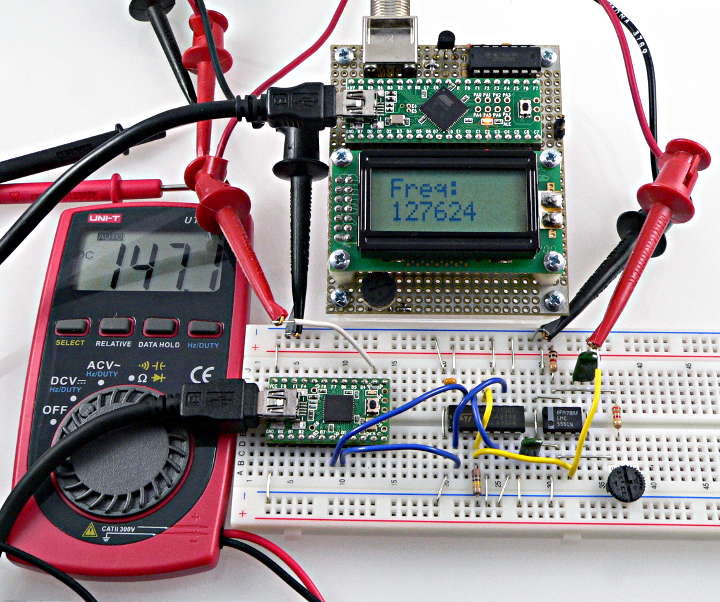 SpeedTest: 147 mV (close to zero CPU remaining) at 127 kHz interrupt rate. |
If using a mechanical system where you reach a speed limit imposed by your motors or other hardware, the amount this voltage has decreased, compared to the baseline, should give you a good approximation of the portion of available CPU time Encoder is consuming at your maximum speed.
Low Performance Polling Mode
If neither pin has interrupt capability, Encoder can still work. The signals are only checked during each use of the read() function. As long as your program continues to call read() quickly enough, you will get accurate results. Low resolution rotary encoders used for dials or knobs turned only by human fingers are good candidates for low performance polling mode. High resolution encoders attached to motors usually require interrupts!With Arduino Uno, Duemilanove or Mega, Serial.print() can cause trouble. Arduino 1.0 provides transmit buffering, which works much better than Arduino 0023 and earlier. With either, a high speed baud rate should be used, and minimizing the amount of data transmitted helps.
As of January 2012, Chipkit does not support attachInterrupt's CHANGE mode so low performance polling mode is always used. Chipkit's Serial.print() lacks transmit buffering (same issue as Arduino Uno on pre-1.0 Arduino). Chipkit does not support the pullup resistors, so you must provide real resistors on both signals. The Chipkit developers have been contacted regarding these issues. Hopefully future versions of MPIDE will fix these problems.
Other Encoder Pages
Wiring's Encoder Library is similar to this library. It only works with Wiring.This Arduino Playground page has the most info and example code.
More links:

http://arduino.cc/playground/Main/RotaryEncoderAcceleration
http://www.circuitsathome.com/mcu/reading-rotary-encoder-on-arduino
http://www.marginallyclever.com/2011/03/using-a-rotary-encoder-with-arduino/
http://hacks.ayars.org/2009/12/using-quadrature-encoder-rotary-switch.html
http://www.helicron.net/avr/quadrature/