Wire Library
The Wire library allows you to communicate with I2C devices, often also called "2 wire" or "TWI" (Two Wire Interface).Download: Wire is included with Arduino
Richard Gemmell has written an improved I2C library for Teensy 4.0.
Brian "nox771" has written an improved I2C library for Teensy 3.0.
Hardware Requirements
I2C devices communicate with 2 signals, called SDA and SCL. Normally a 4.7K pullup resistor is connected between each signal and power (+3.3V on Teensy 3.0, +5V on Teensy 2.0). On Teensy 2.0, 4.0, and 4.1, the weak internal pullup resistors may be sufficient for short wires to a single device. Because the internal resistors are so weak, communication may be slower or unreliable if the wires are long.
| Board | Port Name | Default SDA Pin | Default SCL Pin | Alternate SDA Pin | Alternate SCL Pin | Notes |
|---|---|---|---|---|---|---|
| Teensy 2.0 | Wire | 6 | 5 | |||
| Teensy++ 2.0 | Wire | 1 | 0 | |||
| Teensy LC | Wire | 18 | 19 | 17 | 16 | |
| Wire1 | 23 | 22 | edit WireKinetis.h to use | |||
| Teensy 3.0 | Wire | 18 | 19 | 17 | 16 | |
| Teensy 3.2 | Wire | 18 | 19 | 17 | 16 | |
| Wire1 | 30 | 29 | ||||
| Teensy 3.5 | Wire | 18 | 19 | 8, 17, 34, 48 | 7, 16, 33, 47 | |
| Wire1 | 38 | 37 | ||||
| Wire2 | 4 | 3 | ||||
| Teensy 3.6 | Wire | 18 | 19 | 8, 17, 34, 48 | 7, 16, 33, 47 | |
| Wire1 | 38 | 37 | ||||
| Wire2 | 4 | 3 | ||||
| Wire3 | 56 | 57 | edit WireKinetis.h to use | |||
| Teensy 4.0 | Wire | 18 | 19 | |||
| Wire1 | 17 | 16 | 36 | 37 | ||
| Wire2 | 25 | 24 | ||||
| MicroMod Teensy | Wire | 18 | 19 | |||
| Wire1 | 25 | 24 | ||||
| Wire2 | 17 | 16 | 36 | 37 | ||
| Wire3 | 41 | 40 | ||||
| Teensy 4.1 | Wire | 18 | 19 | |||
| Wire1 | 17 | 16 | 44 | 45 | ||
| Wire2 | 25 | 24 |
Teensy LC & 3.0-3.6 requires pullup resistors to +3.3V. The on-chip pullups are not used.
1K to 4.7K resistors are recommended for most applications. The on-chip pullup resistors in Teensy 2.0, Teensy 4.0, Teensy 4.1 are very weak. Usually communication with 1 chip at 100kHz can work, but with poor signal quality. The on-chip resistors are not enough for several chips or higher speeds.
The Wire library is not compatible with Teensy 1.0.
Basic Usage
Wire.begin()Begin using Wire in master mode, where you will initiate and control data transfers. This is the most common use when interfacing with most I2C peripheral chips.
Wire.begin(address)Begin using Wire in slave mode, where you will respond at "address" when other I2C masters chips initiate communication.
Transmitting
Wire.beginTransmission(address)Start a new transmission to a device at "address". Master mode is used.
Wire.write(data)Send data. In master mode, beginTransmission must be called first.
Wire.endTransmission()In master mode, this ends the transmission and causes all buffered data to be sent.
Receiving
Wire.requestFrom(address, count)Read "count" bytes from a device at "address". Master mode is used.
Wire.available()Retuns the number of bytes available by calling receive.
Wire.read()Receive 1 byte.
Pin Configuration (Teensy LC & 3.x & 4.x)
Wire.setSDA(pin)Configure the pin used for data. Possible alternate pins are shown on the pinout card. This function may be called before or after Wire.begin(). All pins used must have real pullup resistors.
Wire.setSCL(pin)Configure the pin used for clock. Possible alternate pins are shown on the pinout card. This function may be called before or after Wire.begin(). All pins used must have real pullup resistors.
Use of Other I2C Ports
To use the other ports, replace Wire with Wire1, Wire2, Wire3. On Teensy LC & 3.6 use of the last port requires editing WireKinetis.h.With libraries that use Wire to access hardware, look for a begin() function or way to create that's library's instance to specify which port. For example, Adafruit_SSD1306.h allows creating your display instance this way:
Adafruit_SSD1306 myDisplay(128, 64, &Wire1, -1);
For libraries which does not provide a way to configure which port they use, your only option may be to edit the library code, replacing all Wire with Wire1 or Wire2.
Responding in Slave Mode
Wire.OnReceive(myReceiveHandlerFunction)Causes "myReceiveHandlerFunction" to be called when a master device sends data. This only works in slave mode.
Wire.OnRequest(myRequestHandlerFunction)Causes "myRequestHandlerFunction" to be called when a master device wishes to read data. This only works in slave mode.
Example Program
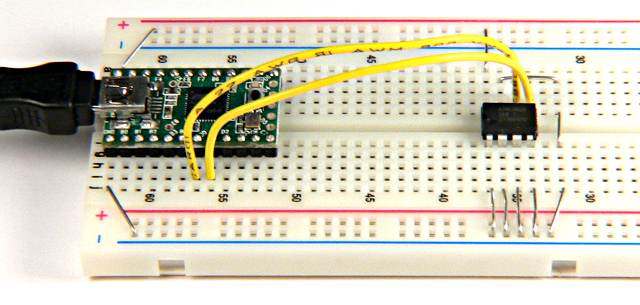
This simple example uses a 24C256 I2C EEPROM. The first byte is read, incremented, and written back.
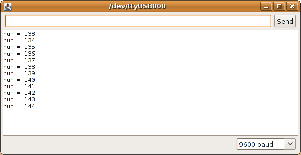
#include <Wire.h>

void setup()
{
  Wire.begin();
  Serial.begin(9600);
}

void loop()
{
  byte num=0;

  // set the 24C256 eeprom address to 0
  Wire.beginTransmission(80);
  Wire.write(0);  // address high byte
  Wire.write(0);  // address low byte
  Wire.endTransmission();

  // read 1 byte, from address 0
  Wire.requestFrom(80, 1);
  while(Wire.available()) {
    num = Wire.read();
  }
  Serial.print("num = ");
  Serial.println(num, DEC);

  // increment num
  num = num + 1;

  // write "num" to 24C256 eeprom at address zero
  Wire.beginTransmission(80);
  Wire.write(0);    // address high byte
  Wire.write(0);    // address low byte
  Wire.write(num);  // any more send starts writing
  Wire.endTransmission();

  // next time loop runs, it should retrieve the
  // same number it wrote last time... even if you
  // shut off the power
  delay(5000);
}
Scanner Program
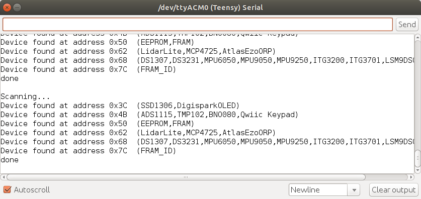
The Wire library comes with an example program which scans for all I2C devices. Open it from File > Examples > Wire > Scanner.
Using Addresses
Many datasheets will document I2C addresses as 8 bit numbers including a R/W bit. Here is an excerpt from the AT24C256B datasheet, the chip used in the example above.
The Wire library requires addresses which do not include the R/W bit. Based only on the datasheet, you might conclude the address is 160 when writing and 161 when reading. The Wire library needs address 80 to communicate with this chip. The R/W bit is automatically created based on your use of the send or receive functions.