Using Digital I/O Pins
| ||||||||||||||||||||||||||||||||||||||||||||||||||||||||||||||||||||||||||||||||||||||||||||||||||||||||||||||||||||||||||||||||||||||||||||||||||||||||||||
|
* LED (LOW=on, HIGH=off) + HWB (bootloader select) |
You can access the pins by their number, or using their pre-defined names shown in the table. These names match the printing on the circuit board.
Input vs Output: pinMode()
When your sketch begins running, all digital pins default to input mode.You can control the mode of any pin using the pinMode() function. For example:
pinMode(PIN_D6, OUTPUT);
The first parameter is the pin number to configure and the second parameter must be either INPUT or OUTPUT.
Often pinMode() is used in the setup() section to configure all the digitial pins that are used and they simply remain that way. However, you may change any pin at any time.
Output: digitalWrite()
When a pin is configured as output, you can make it high or low by calling digitialWrite().
  digitalWrite(PIN_D6, LOW);  // LED on

  digitalWrite(PIN_D6, HIGH); // LED off
Output: digitalToggle()
When a pin is configured as output, you can change its state using digitalToggle(pin).Input: digitalRead()
When a pin is configured as an input, you can read it with digitalRead(), which returns 0 if the pin is low, or 1 if the pin is high. The result is usually used with an if statement to run different code depending on the voltage on the pin.if (digitalRead(PIN_C2)) { // do this if C2 is high } else { // do this if C2 is low }
Input With Pullup
All of the pins have a pullup resistor which may be activated when the pin is an input. Just use pinMode() with INPUT_PULLUP.pinMode(PIN_D7, INPUT_PULLUP);The pullup resistors are useful when connecting pushbuttons that can connect the pin to ground (low), but when the button is not pressed there is no connection at all. The pullup resistor causes the voltage to be high when nothing is connected.
A brief delay may be needed between pinMode() configuring INPUT_PULLUP mode and digitalRead() reporting the unconnected pin as HIGH. The pullup resistor raises the voltage slowly, depending on capacitance of any circuitry attached, plus the capacitance of the pin and breadboard or wires. Usually delayMicroseconds(10) is plenty.
Active Low vs Active High
Intuitively, most people think of a logic HIGH signal to mean "on" or "active" and a logic LOW signal to mean "off" or "inactive". This scheme is called "Active High". However, the opposite scheme is often used in electronic circuits."Active Low" may seem backwards, but is often used because the transistors that cause the signal to be low are more efficient. Some chips, such as infrared receiver modules, have "open collector" outputs, which simply means they work the same way as the pushbutton, where they connect to ground but do not include the ability to output a high signal at all. Because this signal type is so common, every pin includes the optional pullup resistor.
Most projects end up using Active High for some signals and Active Low for others. A common convention is to draw a line over the top of the signal name if it is Active Low.
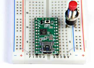
A Complete Example
This simple example blinks the LED slowly when the pushbutton is not pressed, and blinks rapidly when it is pressed. The pushbutton is connected to the D7 pin and ground, and the pullup resistor is used to make the pin high when the button is not connecting it to ground.void setup() { pinMode(PIN_D6, OUTPUT); // LED pinMode(PIN_D7, INPUT_PULLUP); // Pushbutton } void loop() { if (digitalRead(PIN_D7)) { // D7 pin is high due to pullup resistor digitalWrite(PIN_D6, LOW); // LED on delay(400); // Slow blink digitalWrite(PIN_D6, HIGH); // LED off delay(400); } else { // D7 pin is low due to pushbutton pressed digitalWrite(PIN_D6, LOW); // LED on delay(80); // Fast blink digitalWrite(PIN_D6, HIGH); // LED off delay(80); } }This very simple code only tests the D7 pin at the beginning of each blink. If a slow blink begins just before the button is pressed, there is a noticable lag time until the rapid blinking begins. A more sophisticated approach would involve writing a custom delay function that immediately aborts if the D7 pin changes.
TODO: link to page about timekeeping and delay functions (when it's written)