Use this OctoWS2811 Adaptor board for
reliable communication from Teensy 3.2 to large LED projects.
OctoWS2811 is a high performance WS2811 & WS2812 & WS2812B LED library, written by Paul Stoffregen,
featuring simultaneous update to 8 LED strips using efficient
DMA-based data transfer
(technical details below). Minimal CPU impact and double
buffering allows complex animation. A VideoDisplay
example is included, capable of
scaling to extremely large LED installations using multiple Teensy 3.x boards
with a frame sync signal for precise refresh timing.
Update: Some of the latest WS2812B LED strips
require 5 volt signals. You MUST use a 74HCT245 or similar buffer chip to increase Teensy's
3.3V signal to 5 volts for compatibility with these newer WS2812B LED strips.
The OctoWS2811 Adaptor board or similar
5V buffer hardware must be used for reliable signals to large LED projects.
OctoWS2811 requires the DMA (Direct Memory Access) engine which is available
only in Teensy LC & 3.x & 4.x.
Teensy 4.x boards support use of any set of pins, not limited to only 8 fixed pins.
Safety First
LEDs can produce extremely bright light. Please use caution when viewing
large numbers of LEDs at close distance. A
diffusing material in front the LEDs is usually a good idea.
Large LED arrays consume considerable power. Appropriate wiring should
be used. AC mains voltage should be wired properly according to electrical codes.
Hardware Requirements
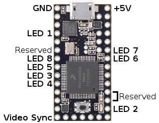
Eight LED strips should be connected as shown. Fewer or shorter strips
may be used, with addressing described below.
Teensy LC Pin
Teensy 3.0 Pin
Teensy 3.1 & 3.2 Pin
Teensy 3.5 & 3.6 Pin
Teensy 4.0 & 4.1 Pin**
Function
2
2
2
2
2
LED Strip #1
14
14
14
14
14
LED Strip #2
7
7
7
7
7
LED Strip #3
8
8
8
8
8
LED Strip #4
6
6
6
6
6
LED Strip #5
20
20
20
20
20
LED Strip #6
21
21
21
21
21
LED Strip #7
5
5
5
5
5
LED Strip #8
-
-
-
-
-
Connect together
-
4
32
-
-
Do not use
3, 4
3
25
29, 30
-
Do not use as PWM
12*
12*
12*
12*
12*
Frame Sync (Video)
TPM2
FTM1
FTM2
FTM2
QTimer4
Timer Hardware Used
* Pin 12 only used by VideoDisplay example ** Default pins when custom pin list is not used
Teensy 4.0 and Teensy 4.1 can use any group of pins, even groups smaller or
larger than 8 pins! In Arduino, open File > Examples > OctoWS2811 > Teensy4_PinList
for details. If a custom pin list is not specified, the same group of 8 pins
as Teensy 3.x will be used by default.
OctoWS2811 uses internally uses a timer, and a PWM waveform at a pin on some
boards. This PWM pin and the timer must not be used. See the table above for
details.
Early versions of OctoWS2811 required pins 15 & 16 to be connected together.
Modern versions do not use pin 15 or 16.
Approximately 1000 LEDs per Teensy 3.0 or 4000 LEDs per Teensy 3.2
are recommended for large LED projects,
to maintain high performance. Any number of Teensy boards may be used
to support large LED arrays.
The video frame sync signal must be connected to pin 12 of all the boards.
Create OctoWS2811 object. You can only create a single object, but it
must be created with these parameters:
ledsPerStrip: The number of LEDs connected to each pin, or maximum number
if different on each pin.
displayMemory: The memory used for display data. Use an array of "int" 6 times
ledsPerStrip.
drawingMemory: The memory used for drawing operations. Use either an array of
"int" 6 times ledsPerStrip, or NULL to perform all drawing directly to the display
memory.
config: Configure the WS2811 speed and LED color order. Options are
WS2811_RGB, WS2811_RBG, WS2811_GRB, WS2811_GBR, WS2811_800kHz, WS2811_400kHz.
leds.begin();
Initialize the library. This must be called before using
setPixel or show.
leds.setPixel(num, red, green, blue);
Set a pixel. Red, green and blue are 0 to 255.
leds.setPixel(num, color);
Set a pixel. Color is a 24 bit color in RGB order (the same as html).
leds.show();
Start an update of the LEDs. This function returns within
2 microseconds. The display update continues, taking 30 microseconds for
for each LED, plus 50 microseconds to reset the WS2811. If called while
a previous update is running, this function waits for previous update
to complete and then starts a new update.
leds.busy();
Check if a previous show() is still running. Returns true
if the WS2811 LEDs are busy being updated, or false if no update is in
progress.
leds.getPixel(num);
Read a pixel's color. The return is a 24 bit color number.
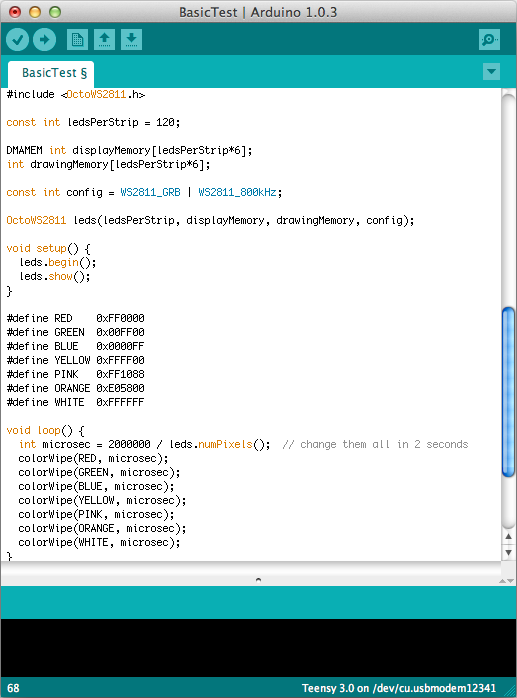
BasicTest Example Program
BasicTest can be loaded from File > Examples > OctoWS2811 > BasicTest.
The BasicTest is useful to verify your LEDs work, and to find the correct color
configuration. Most WS2811 LEDs are wired for WS2811_GRB. If yours have different
wiring, the colors will appear in a different order.
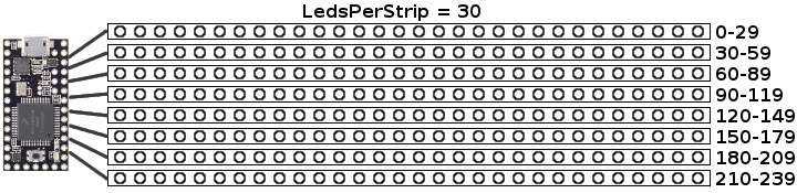
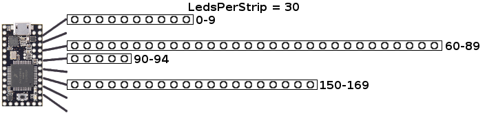
OctoWS2811 is designed to drive 8 LED strips of equal length. LEDs
on the first strip are numbered starting at zero. The second strip
begins at the strip length and goes to strip length minus 1, and
so on for each strip.
Shorter strips may be used on some or all 8 outputs. Outputs may
be left unused. The LED addresses for setPixel() and getPixel()
are the same as if 8 full length strips had been connected.
Even if fewer LEDs are connected, OctoWS2811 must be initialized
with a memory buffer of 6 integers per LED in the configured strip
length. Using shorter strips uses memory inefficiently, but can
be done if fewer than 8 full length strips are needed.
The VideoDisplay example can show a video file streamed from a PC, Mac,
Raspberry Pi or similar computer. One or more Teensy 3.0 boards running
VideoDisplay can receive the streaming video, allow construction of
very large LED arrays!
For best performance, connect
approximately 1000 WS2811 LEDs per Teensy 3.0.
When using more than 1 board, the video Frame Sync (pin 12) signal must be
connected to all boards.
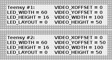
VideoDisplay with 1920 LEDs (60x32) driven by two Teensy 3.0 boards.
The code can be loaded from File > Examples > OctoWS2811 > VideoDisplay.
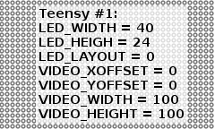
For each Teensy running VideoDisplay, you must configure seven parameters.
The parameters are configured by editing the VideoDisplay.ino example.
#include <OctoWS2811.h>
// The actual arrangement of the LEDs connected to this Teensy 3.0 board.
#define LED_WIDTH 60 // number of LEDs horizontally
#define LED_HEIGHT 16 // number of LEDs vertically (must be multiple of 8)
#define LED_LAYOUT 0 // 0 = even rows left->right, 1 = even rows right->left// The portion of the video image to show on this set of LEDs. All 4 numbers// are percentages, from 0 to 100.
#define VIDEO_XOFFSET 0
#define VIDEO_YOFFSET 0 // display entire image (single Teensy)
#define VIDEO_WIDTH 100
#define VIDEO_HEIGHT 100
When using more than one Teensy, each is configured for the LEDs it drives.
Parameters
Function
LED_WIDTH, LED_HEIGHT
The number of LEDs connected to each individual Teensy 3.0.
LED_HEIGHT must be a multiple of 8.
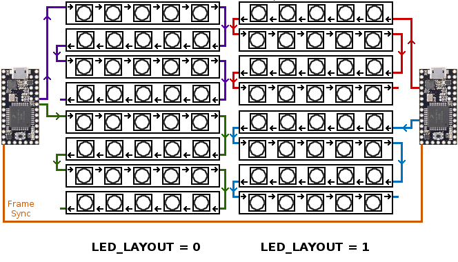
LED_LAYOUT
Zig-Zag layout of rows from each strip.
0 = Left->Right, then Right->Left
1 = Right->Left, then Left->Right
VIDEO_XOFFSET, VIDEO_YOFFSET
The upper right corner of the portion of the video this Teensy
should display. These numbers are percentages, from 0 to 100.
When using only one Teensy, set these to 0, 0.
VIDEO_WIDTH, VIDEO_HEIGHT
The size of portion of the video this Teensy
should display. These numbers are percentages, from 0 to 100.
When using only one Teensy, set these to 100, 100.
The LED_LAYOUT setting configures which direction the LEDs are
physically arranged. If LED_HEIGHT is 8 (each strip is a single row),
then 0 means the LEDs are left to right, and 1 means they are right
to left oriented.
When LED_HEIGHT is 16, 24, 32, etc, each strip of LEDs forms multiple
rows in a zig-zag layout. LED_LAYOUT = 0 means the leds go left
to right, then right to left, and so on. Typically LED_LAYOUT = 0
is used when Teensy 3.0 is located on the left side of the display,
and LED_LAYOUT = 1 is used when Teensy is on the right side. A
very large LED project may use both layouts, where several boards
drive the LEDs from both sides.
Each Teensy must also be configured with information about the
portion of the video frame it should display. The video transmit
application queries this information, for a "plug and play" style
automatic configuration, even if your operating system assigns
the serial device names or COM port numbers differently.
40x24 LEDs using one Teensy 3.0
These parameters allow you to easily construct large LED
arrays by using multiple boards.
60x32 LEDs using two Teensy 3.0s
With each Teensy 3.0 driving approximately 1000 LEDs (or less),
you can scale up to a very large high performance LED array!
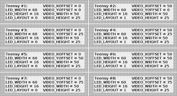
120x64 LEDs using eight Teensy 3.0s
When using more than one Teensy, connect the Frame Sync (pin 12)
signal between all boards. The first board will output a pulse
and the others will synchronize their WS2811 update, for a very
accurately timed update of the entire LED array.
For programming several Teensy 3.0s, the simplest way is to edit
the VideoDisplay.ino parameters, click Verify, and then press the
pushbutton on the desired board for those parameters, repeating
for each board in the array.
The movie2serial Processing program can transmit video data to
any number of Teensy boards running the VideoDisplay code. It
is included inside the VideoDisplay example folder.
Processing is an open
source programming environment. Arduino is based on Processing,
so they share a similar user interface.
Processing programs run on your computer, usually for graphics.
Processing can transmit video to any number of Teensy 3.0 boards.
Movie2serial receives most configuration information by querying
the parameters stored in each Teensy. However, a few settings
must be edited:
edit myMovie to the video file to play.
edit the port names on the serialConfigure lines in setup().
(optional) if your LED strips have unusual wiring, edit colorWiring()
(optional) if playing 50 or 60 Hz progressive video (or faster), edit framerate.
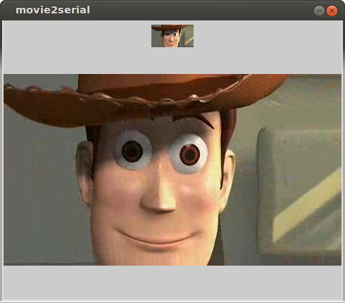
movie2serial program
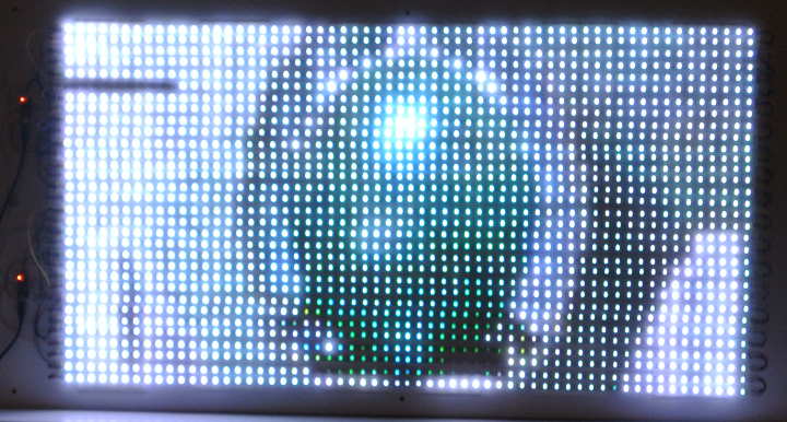
The large image is the original video file. The small icon-size image
above is the actual image sent to the LEDs. 1920 is a large number
of LEDs, but relatively low image resolution for video.
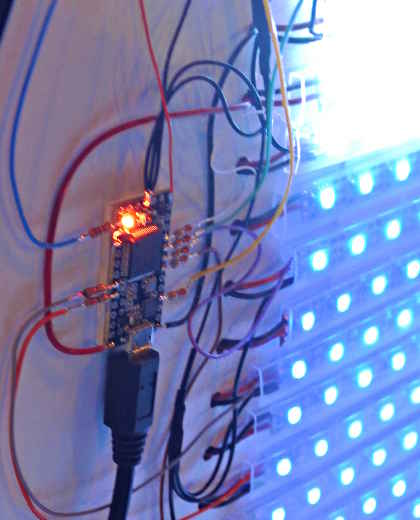
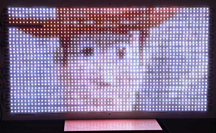
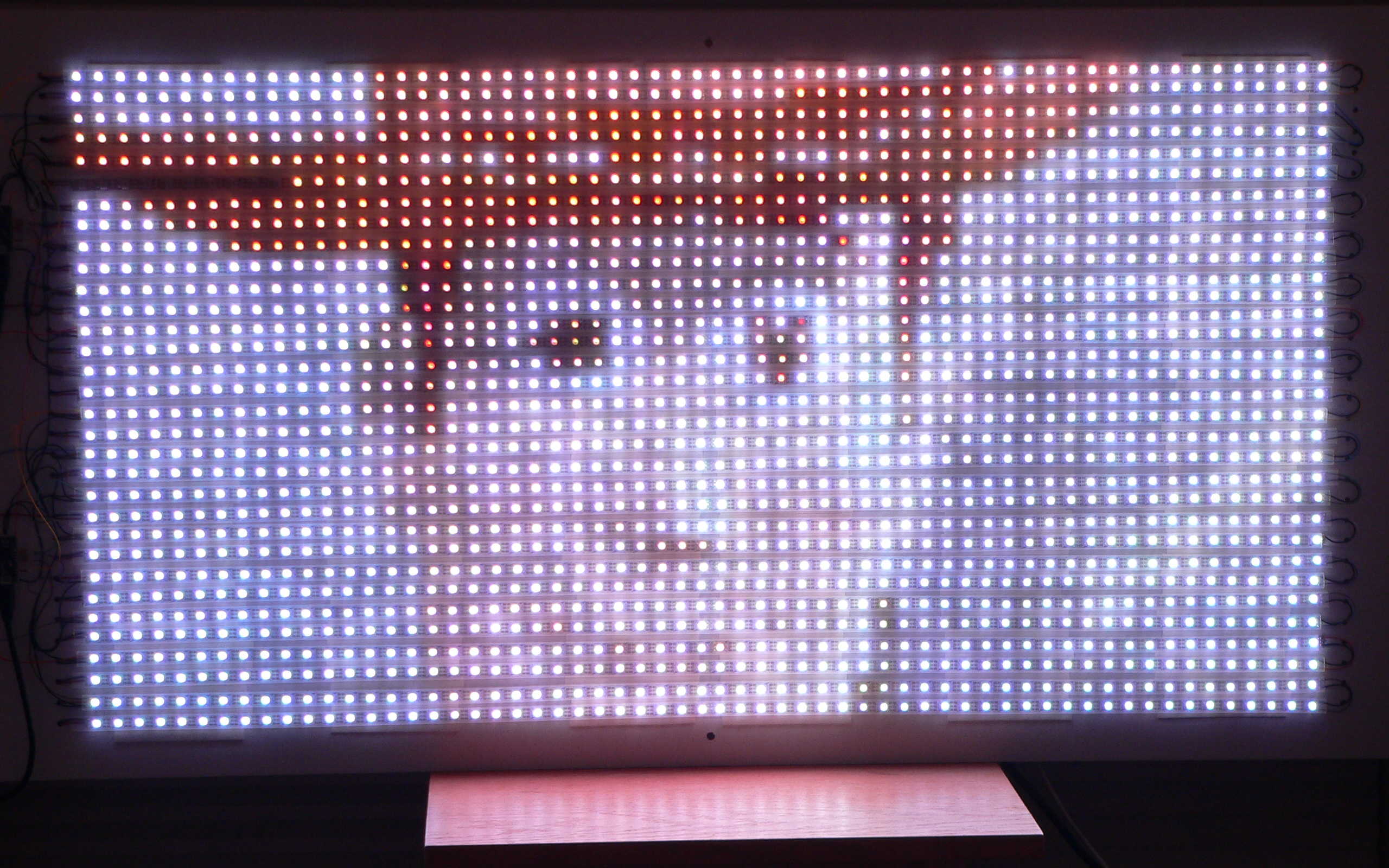
This last photo was taken in a brightly lit room. The LEDs are
incredibly bright, forcing the camera to low exposure, making the
room look nearly pitch-black dark. Cameras really can't capture
the live awesomeness of thousands of LEDs!
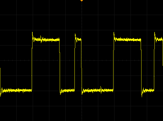
Signal Quality
While testing OctoWS2811, the 5 volt WS2811 chips were able to work with
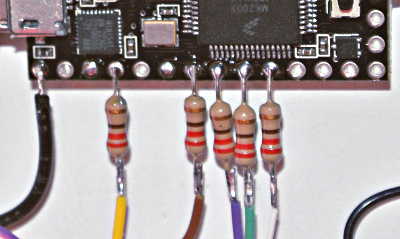
Teensy 3.0's 3.3 volt output signals. However, a series resistor
located close to the Teensy 3.0 pin
is often necessary to reduce ringing and cross-coupled signals.
Signal after 12 inches of wire
With 220 ohm resistor added
The series resistors help match Teensy's outputs to the
characteristic impedance of your wiring. The best value to
use depends on the type of wire and its spacing to nearby
ground wires. Values in the range of 47 to 220 ohms are
probably best.
Update: This OctoWS2811 Adaptor
is now available, with the 74HCT245 buffer chip, 100 ohm resistors, and
RJ-45 jacks for CAT6 cable, which exactly matches 100 ohm resistors. This
adaptor is highly recommended for any large LED project. Please also follow
its wiring recommendations, where the LED power supplies are located close to
the LED strips using short wires for the power, and signal grounds from Teensy
meet the power ground at or near the LED strip data inputs.
Place resistors close to the Teensy pins.
The WS2811 input high specification of "0.7*VDD".
To truly meet this requirement, a buffer chip should be used to
convert the 3.3 volt signal to 5 volts. A 74HCT245 is recommended.
Ryan wrote a
detailed post about signal quality
on the forum, with great investigation into signal corruption effects involving
multiple power supplies, different resistors, and other issues. For anyone building
a very large OctoWS2811-based installation, Ryan's writeup is worth reading!
Teensy 3.0 Power
Usually Teensy 3.0 should be powered by the same +5 volt power
supply as the WS2811 LEDs. By default, Teensy 3.0 has VUSB connected
to VIN. They can be separated by cutting apart pads on the bottom
side of the board.
Power by VIN, not VUSB
Once cut apart, it is safe to apply +5 volt power to VIN. The
USB cable will not attempt to power the LEDs, and the power supply
will not feed power back to your computer.
When Teensy is powered by VIN, you can only load new code when
VIN has power, because VUSB is disconnected.
When illuminated at full brightness, each LED can consume approximately
0.25 Watts of power. For a large LED array, a very substantial 5 volt
power source is required.
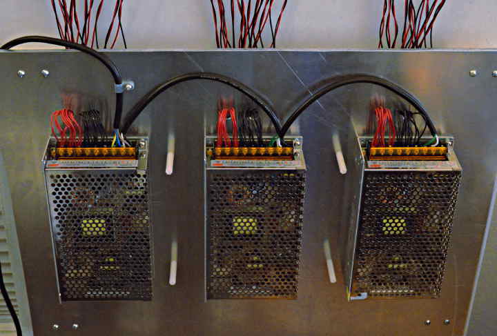
Three 5V, 40A power supplies used for 1920 LEDs
The 3 power supplies show above are some of the cheapest available from
Ebay and Alibaba merchants. They must be attached to a large metal
surface for adequate cooling. These 3 units arrived with their
120/240 volt input select switch missing (effectively leaving them in
240 volt mode, only able to run about 10% before losing regulation with
120 volts input).
Caution: ATX power supplies meant for PC computers are usually
designed to deliver most of their power to the 12V lines. Even if the
5V output is rated for many amps, it may not be stable when there is
no load on the 12V lines. Even name brand PC power supplies do this.
In one severe case, the 5V line spiked to at least 9 volts, destroying
a Teensy 3.0 board. Caution is advised with using any ATX power supply.
A strip of 60 LEDs can draw about 3 amps of current. Each strip should
have its own connection directly to the power supply, using #22 or larger
wire to avoid loss of voltage. Power can travel through about 2 meters
of LED strip. If longer strips are used, both ends should be connected
by wires directly to the power supply.
The LED power and Teensy 3.0 must have their grounds connected together.
A very large LED array can consume a tremendous amount of power. A standard
120V USA mains outlet can provide enough power for about 6000 LEDs. When
building larger arrays, a 240 volt line may be needed.
Cheap power supplies lacking active power factor correction, when used in
large numbers, may result is a very large inrush current surge when the
AC power is applied. Extremely large LED projects should consider power
supplies with inrush limiting and power factor correction. Also, if you build
such an awesome LED project, please send photos!
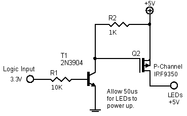
WS2811 Idle Power
When the LED is off, the WS2811 chip consumes approximately 0.9 mA of
current. For battery powered LEDs, this current can easily drain the
battery. A P-channel MOSFET transistor or similar switch may be needed
to disconnect power from the LEDs, if the battery remains connected
when the LEDs are not in use.
This circuit was recommended by David Beaudry to manage the power.
David also tested Vishay SUP75P03-07-E3 and SI4465ADY-T1-E3 transistors,
which are able to power more LEDs.
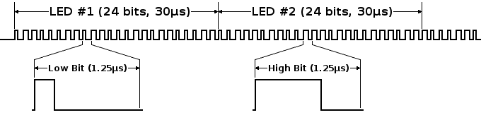
OctoWS2811 is designed for highly efficient data output to WS2811-based
LEDs, able scale to very large LED arrays. The WS2811 requires very
specific waveform timing. Each LED uses 24 bits, each 1.25
µs, for a total of 30 µs per LED in the strip.
Driving 8 LED strips simultaneously allows each strip to be only 1/8th
the length. All LEDs update 8X faster than driving only a
single long strip. 1000 LEDs can be updated in 3.8 ms, which allows a
theoretical update rate of 240 Hz.
The VideoDisplay example implements a Frame Sync signal, allowing many
Teensy 3.0 boards to work together, each driving 1000 LEDs. The boards
precisely synchronize their update, even if the USB delivers data to the
many boards with some varying latency. Fast update times are preserved
when scaling up to extremely large LED arrays.
OctoWS2811 uses Direct Memory Access (DMA) to create the WS2811
waveforms with nearly zero CPU usage. Because the CPU is free and interrupts
remain enabled, the processor is free to receive data or perform
computations in preparation for the next frame of display, while the
previous one is still be transferred to the LEDs. The 8X faster update
and free CPU time
the key differences between OctoWS2811 and other libraries, which create
the WS2811 waveforms for a single strip using carefully timed software.
DMA is a special hardware feature which allows data to be automatically
moved between memory and I/O registers in response to hardware events,
without any CPU usage (other than initially configuring parameters).
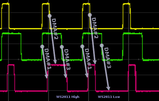
OctoWS2811 uses 3 DMA channels to synthesize the WS2811 waveforms.
Three DMA Channels Synthesize WS2811 Waveform
The hardware events which trigger the DMA channels are a pair of PWM
waveforms, corresponding to the WS2811 bit low and high waveforms.
The rising edge (both PWM rise at the same moment) triggers channel #1,
which copies a fixed byte (0xFF) to an I/O register which sets all 8
output bits, causing the WS2811 waveform to begin each bit. The first
falling edge triggers DMA channel #2, which copies one byte of the actual
frame buffer data to all 8 pins. The bits which are low transition to
low at the correct time to create a zero bit to each WS2811 LED. The
bits that are high have no effect, because channel #1 already set all
8 pins high. The 3rd DMA channel triggers at the second falling PWM edge,
causing all the WS2811 bits to be written to zeros. The pins which
were left high by channel #2, become low, as required by the WS2811
timing for a one bit. The pins which were already low are not changed.
Together, these 3 I/O updates create a WS2811 waveform automatically
without any CPU activity.
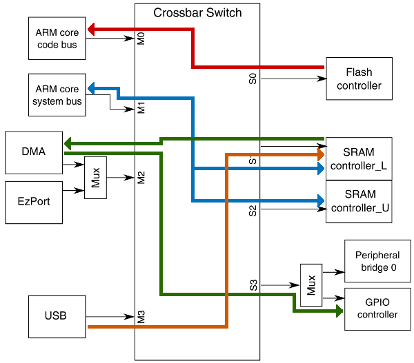
The ARM-based chip from Freescale used on Teensy 3.0 has crossbar
switch and dual-bus RAM, which allows the DMA and ARM CPU to work
together very efficiently.
Data flow with OctoWS2811
The crossbar switch allows 4 separate bus masters to access 4 different
bus devices simultaneously. Only when 2 bus masters wish to access the
same device at the same time is one master made to wait.
OctoWS2811 utilizes the dual-bus RAM and crossbar switch for maximum
efficiency. The
display memory is declared with "DMAMEM", which forces that memory
to be allocated in the lower half of the RAM. USB buffers are also
allocated in the lower RAM. The CPU accesses both, but the heavily
used stack memory for local variables and temporary data is
located in the upper RAM, which minimizes wait-inducing conflicts
between the CPU and DMA. During normal operation, the CPU primarily
accesses the upper RAM through a dedicated channel in the crossbar
switch, which the DMA is able to read the lower half RAM and write
to the I/O registers, also through crossbar switch paths that do not
impact the ARM CPU's access to code and the most commonly accessed data.
Of course, the USB also utilizes its own built-in DMA to transfer
incoming data very efficiently into the lower RAM area.
Extremely efficient synthesis of the tight-timing WS2811 waveforms,
with almost zero impact to the CPU is the primary benefit of OctoWS2811.
The fast 32 bit CPU is fully available to prepare the next display frame.
Interrupts remain enabled during transfers, allowing serial protocols
like DMX to work. These features together with 8X faster updates and
scalability to use many boards give OctoWS2811 the ability to make
extremely large LED arrays very easy to implement with very high
performance!
GreeLED is a Chinese manufacturer,
usually the first to introduce newest LED products. They will sell small
quantities to individuals, but you may need to send funds by wire transfer?
Alibaba/Aliexpress is a site offering
consumer-level access to Asian vendors with great prices. Search for "WS2811".
Many of them seem to be "Ray Wu". Usually you can expect fast shipping, but
little or no post-sale service or technical support.
Ebay has many vendors reselling WS2811
LED products. If you prefer to use Paypal, Ebay may be the easist path.
Like Alibaba, there is usually little or no post-sale service or support.
Most of these vendors also sell power supplies useful for LED projects.
For large LED project, you should purchase spares, especially if buying
a large number of LEDs from an Alibaba or Ebay vendor. Numerous people have
reported on forums a small number of bad LEDs within a large batch.
The 1920 LED array
PJRC constructed to develop and test this library has 3 LEDs that stop working
after some time (perhaps overheating) and impact all others after them on the strip.
One stops working within minutes, the others after a couple hours of use. These LEDs
were purchased from Ray Wu via Aliexpress.
It's possible to cut the strip and solder a
replacement LED in, but only if you have spares on-hand.


