|
|
This is an archived copy of the work done
by Brad Baird, Tom Freestone, Derek Joos, Steve Saunders, and Ryan
Woodings to attempt to add ATAPI support to the PJRC MP3 player.
This is their original web
page.
It seemed like a good idea to archive a copy, since these student web
pages usually disappear after a while. Here is
the final code they wrote.
ATA and ATAPI Overview:
 Officially the name of the IDE
interface is
AT-Attachment (ATA). It was
developed
and championed by Compaq in 1984.
Compaq contacted Western Digital (Hard Disk controller
manufacturer) to build
a controller that could be mounted directly on the hard disk.� In 1985, this became an actuality
when
Imprimis (CDC) began producing drives with onboard controllers for
Compaq's
personal computers. In a short
period,
many other computer and disk drive manufacturers found IDE/ATA to be
advantageous and began implementing own proprietary flavors.� This resulted in a myriad of
competing "IDE"
solutions. In 1988, in order to
bring
an end to the chaos, ANSI standardized the IDE/ATA interface into
X3.221.1994
standard (ATA-1).
Officially the name of the IDE
interface is
AT-Attachment (ATA). It was
developed
and championed by Compaq in 1984.
Compaq contacted Western Digital (Hard Disk controller
manufacturer) to build
a controller that could be mounted directly on the hard disk.� In 1985, this became an actuality
when
Imprimis (CDC) began producing drives with onboard controllers for
Compaq's
personal computers. In a short
period,
many other computer and disk drive manufacturers found IDE/ATA to be
advantageous and began implementing own proprietary flavors.� This resulted in a myriad of
competing "IDE"
solutions. In 1988, in order to
bring
an end to the chaos, ANSI standardized the IDE/ATA interface into
X3.221.1994
standard (ATA-1).
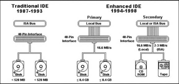
Figure
1 IDE
Configuration [5]
Per the ATA-1 standard, there are two IDE bus configurations (see
figure 1). First, the IDE bus consists of an interface board (IDE
adapter) installed on an ISA bus. Two IDE disk drives connect via a
cable to the adapter. The second configuration is where the host
adapter is installed on any bus that can serve the hard disk through the
IDE interface. A cable attaches the disks to the IDE connector and the
bus. By doing this, it eliminates the need to purchase an IDE adapter
required by the first configuration. The second arrangement is
currently the most popular and is standard with most desktops and
laptops with a PCI bus. The ATA-1 standard stipulated that a ATA bus
only accommodates two drives. These are addressed using 0 (master) and
1 (slave). Since both drives have an onboard controller, each "hears"
all of the IDE commands sent on the IDE bus. Thus, the need is resolved
to determine for whom a command is sent. The ATA-1 specification also
details two transfer modes in which commands and data may be sent to a
disk. These are programmed I/O (PIO) and direct memory access (DMA)
[3].
Since its adoption, there has been an effort to improve the IDE/ATA
interface resulting in several enhancements to the original standard.
The most significant to this project is ATAPI. One of the shortcomings
of the original ATA-1 standard was it only supported hard disks. Other
devices like CD-ROMS, floppies, etc. were attached to proprietary
 interfaces. For instance, many original CD-ROMs were connected directly
to the sound card. In general, these interfaces proved to be slow and
cumbersome. To resolve this, a new standard was accepted called AT
Attachment Packet Interface (ATAPI/SFF-8020). This was designed to
accommodate the aforementioned devices. It allows them to plug directly
into a standard IDE cable and be configured like a ATA drive as a master
or slave [2]. At the physical layer, ATAPI uses the same signaling as
ATA-2. Above that layer, ATAPI and IDE devices are dissimilar. ATAPI
is fundamentally different from ATA (ATA-1, ATA-2, ATA-2) in the way it
operates through the use of command packets. This is the source from
where its name is derived. Similar to the protocol used by SCSI,
packets enable it to use tasks (command register blocks) to communicate
with the disk. With the exception of the physical interface, ATAPI is
closer to SCSI than it is to ATA. However, ATAPI does support a
combination of ATA and SCSI commands. There is
a
difference between ATAPI and native SCSI commands.
ATAPI commands differ because they do not contain a LUN
field or
have a control byte. There is
overlap
between ATAPI supported ATA or SCSI commands.
For instance, the ATA command IDENTIFY DRIVE provides low-level
information about the drive in contrast to the SCSI INQUIRY command
which only
supplies high-level data regarding the disk.
This provides flexibility and slight variation in implementation
solutions and is an advantage of ATAPI [3].
interfaces. For instance, many original CD-ROMs were connected directly
to the sound card. In general, these interfaces proved to be slow and
cumbersome. To resolve this, a new standard was accepted called AT
Attachment Packet Interface (ATAPI/SFF-8020). This was designed to
accommodate the aforementioned devices. It allows them to plug directly
into a standard IDE cable and be configured like a ATA drive as a master
or slave [2]. At the physical layer, ATAPI uses the same signaling as
ATA-2. Above that layer, ATAPI and IDE devices are dissimilar. ATAPI
is fundamentally different from ATA (ATA-1, ATA-2, ATA-2) in the way it
operates through the use of command packets. This is the source from
where its name is derived. Similar to the protocol used by SCSI,
packets enable it to use tasks (command register blocks) to communicate
with the disk. With the exception of the physical interface, ATAPI is
closer to SCSI than it is to ATA. However, ATAPI does support a
combination of ATA and SCSI commands. There is
a
difference between ATAPI and native SCSI commands.
ATAPI commands differ because they do not contain a LUN
field or
have a control byte. There is
overlap
between ATAPI supported ATA or SCSI commands.
For instance, the ATA command IDENTIFY DRIVE provides low-level
information about the drive in contrast to the SCSI INQUIRY command
which only
supplies high-level data regarding the disk.
This provides flexibility and slight variation in implementation
solutions and is an advantage of ATAPI [3].
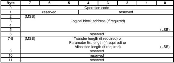
Figure 2 ATAPI Command Packet [6]
The ATAPI transport protocol revolves around the ATAPI PACKET
command. All functions are executed in the same manner as in ATA-2.
This involves using PIO to set the command block and drive bit and to
write the command register. One noticeable difference between ATAPI and
ATA is how command is written with the first DRQ in ATA whereas in ATAPI
the command packet is written instead. The following is the series of
events that must occur to send an ATAPI packet (see figure
3):
-
The host waits until BSY and DRQ are 0 and subsequently initializes the
ATAPI task file. Then it writes the ATAPI PACKET opcode (A0h) into the
command register.
-
The device sets BSY and prepares to accept the command packet proper.
When it is ready it sets COD and cancels IO. Then it sets DRQ and
cancels BSY.
-
As soon as it sees DRQ, the host writes the 12 command bytes into the
data register. After having received the 12th byte the
device cancels DRQ, sets BSY and reads the features and the byte count
from the task file.
-
Let us now assume that we are dealing with a command packet which
entails a data transfer to the host. The device executes the command
and prepares for the data transfer.
-
The device loads the byte count register, sets IO and cancels COD, sets
DRQ and cancels BSY, and finally sets INTRO.
-
As soon as the host sees DRQ, it reads the status register. As a
reaction, the device cancels INTRO. The host reads the data register as
many times as specified in the byte count register. When all data are
read the device negates DRQ.
-
The device writes the final status into the status register, sets COD,
IO, and DRDY and cancels BSY and DRQ. Finally it sets INTRQ.
-
This is the signal for the host to read the final status and, if
necessary, the error register [3].
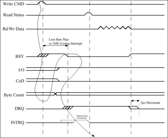
Figure 3 Timing for a Command Packet Transfer [7]
Return to Title Page.
|