Teensy 3.2 & 3.1 - New Features
Teensy 3.2 has dedicated 3.3V regulator.
Teensy 3.1 has gold plating for easier soldering.
Teensy 3.0 has standard tin plating finish.
|
Teensy 3.1 adds several new features, due to an upgraded microcontroller. Here are the highlights. A table of technical specifications is show below.
Teensy 3.2 adds a more powerful 3.3 volt regulator, with the ability to directly power ESP8266 Wifi, WIZ820io Ethernet and other power-hungry 3.3V add-on boards.
More Memory For Awesome Projects
The RAM has quadrupled since 3.0, from 16K to 64K. While 16K is plenty for nearly all Arduino libraries, 64K allows for more advanced applications. Icons and graphics for color displays and audio effects requiring delays, like reverb and chorus, will become possible on Teensy 3.2 & 3.1.Flash memory has also doubled, to 256K, and provides double the memory bandwidth.
5 Volt Tolerance on Digital Inputs
Today most new chips use 3.3V signals, but many legacy products output 5 volt digital signals. These can now be directly connected to Teensy digital inputs.All digital pins are 5 volt tolerant on Teensy 3.2 & 3.1. However, the analog-only pins (A10-A14), AREF, Program and Reset are 3.3V only.
Update: Color Change Jan 22, 2014
The color of Teensy 3.1 was changed from black to green on January 22, 2014.
Before Jan 22 
|
After Jan 22
|
All Teensy 3.2 boards are green.
The green material has slightly higher resolution. See
this post
for details.
12 Bit Analog Output
Teensy 3.2 & 3.1 have a proper analog output. You can always filter PWM, but true analog output responds rapidly. The output is created by the stable reference voltage, so it's doesn't vary if your power supply voltage changes slightly.Normally the DAC is used by the Audio Library, but you can also control it directly if not using audio.
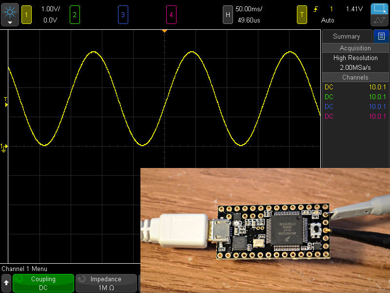
// Simple DAC sine wave test on Teensy 3.1

float phase = 0.0;
float twopi = 3.14159 * 2;
elapsedMicros usec = 0;

void setup() {
  analogWriteResolution(12);
}

void loop() {
  float val = sin(phase) * 2000.0 + 2050.0;
  analogWrite(A14, (int)val);
  phase = phase + 0.02;
  if (phase >= twopi) phase = 0;
  while (usec < 500) ; // wait
  usec = usec - 500;
}
Simply use analogWrite() on the A14 pin for true analog output.
See this forum thread for a more advanced DMA-based example using the DAC.
Two Analog to Digital Converters
With analogRead(), you can measure many signals, but only 1 at a time. Teensy 3.2 & 3.1 has a second ADC, so you can concurrently measure 2 analog signals. For stereo audio or power monitoring, sampling both left and right, or voltage and current at the same moment is very beneficial.Pedvide's ADC library can be used to access both ADCs.
PJRC is developing an advanced analog read function for Arduino, to make using these new analog input capabilities very easy.
CAN Bus
Controller Area Network is a communication used in automobiles. The FlexCAN library (included with the Teensyduino installer) supports use of the CAN controller on Teensy 3.2 & 3.1.Technical Specifications
| Feature | Teensy 3.0 | Teensy 3.2 Teensy 3.1 | Units |
|---|---|---|---|
| Price | 19.00 | 19.80 | US Dollars |
| Processor Core Rated Speed Overclockable |
MK20DX128VLH5 Cortex-M4 48 96 |
MK20DX256VLH7 Cortex-M4 72 96 |
MHz MHz |
| Flash Memory Bandwidth Cache |
128 96 32 |
256 192 256 |
kbytes Mbytes/sec Bytes |
| RAM | 16 | 64 | kbytes |
| EEPROM | 2 | 2 | kbytes |
| Direct Memory Access | 4 | 16 | Channels |
| Digital I/O Voltage Output Voltage Input |
34 3.3V 3.3V Only |
34 3.3V 5V Tolerant |
Pins Volts Volts |
| Analog Input Converters Resolution Usable Prog Gain Amp Touch Sensing Comparators |
14 1 16 13 0 12 2 |
21 2 16 13 2 12 3 |
Pins Bits Bits Pins |
| Analog Output DAC Resolution |
0 - |
1 12 |
Pins Bits |
| Timers FTM Type PWM Outputs PDB Type CMT (infrared) Type LPTMR Type PIT (interval) Type Systick RTC (date/time) ** |
11 Total 2 10 1 1 1 4 1 1 |
12 Total 3 12 1 1 1 4 1 1 |
Pins |
| Communication USB Serial With FIFOs High Res Baud Fast Clock SPI With FIFOs I2C CAN Bus I2S Audio FIFO Size |
1 3 1 3 2 1 1 1 0 1 4 |
1 3 2 3 2 1 1 2 1 1 8 |
|
| ** RTC requires a 32.768 kHz crystal & 3V battery. See the Time Library for details. | |||
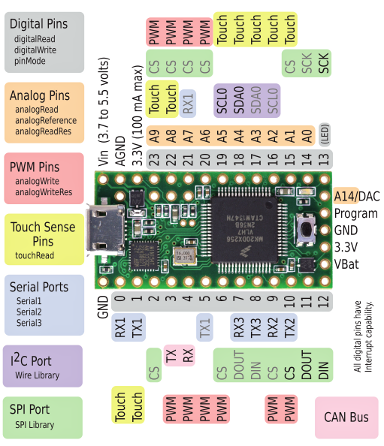
Pinouts
Teensy 3.2 & 3.1 have exactly the same pinout. Teensy 3.2 provides more power on its 3.3V pin, and accepts a wider voltage input range. If used within Teensy 3.1 limits, Teensy 3.2 and 3.1 are interchangeable.Both 3.2 and 3.1 are meant to be a drop-in replacement for Teensy 3.0. Only 1 pin has different functionality. The reset pin was replaced by A14/DAC, which you can use for true analog output, or as another analog input.
| Teensy 3.0 | Teensy 3.1 | Teensy 3.2 | ||
|---|---|---|---|---|
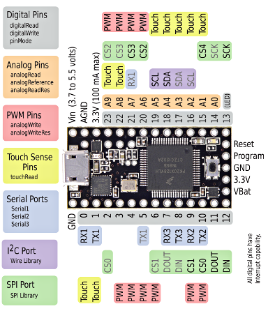 |  | 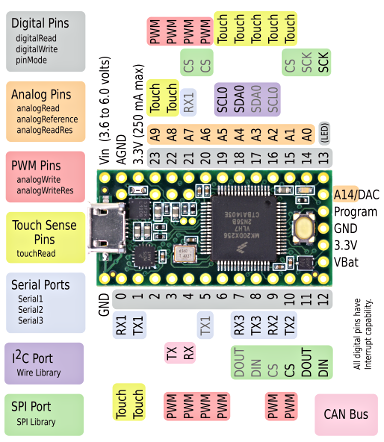 |
Pins 3 and 4 gained CAN bus functions.
Pins 6, 9, 15, and 20-21 can still have SPI chip select capability, but the labels were removed to simplify the pinout card. Currently no libraries use the native chip selects. However, a new SPIFIFO library is in development.
| Teensy 3.0 | Teensy 3.1 | Teensy 3.2 | ||
|---|---|---|---|---|
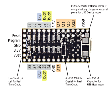 | 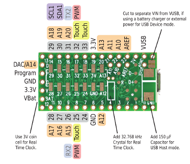 | 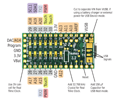 |
On the back side, 2 pins gained new PWM functionality and 6 pins have new analog input capability. A second I2C port is also added.
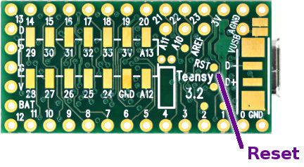
Reset Signal
Teensy 3.0 supported both a Program signal, to reboot into bootloader mode, and a traditional Reset signal, for a conventional reboot that restarts your application.The Reset signal can be found on a new test point on the bottom side of Teensy 3.1.
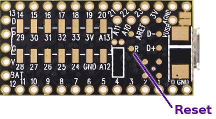
The Reset signal is also available at a test point on the bottom side of Teensy 3.2.