Using Analog Inputs
Teensy 2.0 and Teensy++ 1.0 & 2.0 have a 10 bit analog to digital converter (ADC) which can be used to read analog voltages, such as signals from sensors. Teensy 1.0 does not have analog inputs.
Simple ADC Usage
The simplest way to use the ADC is to manually begin a conversion, wait for it to complete, and read the result.
int16_t adc_read(uint8_t mux)
{
    uint8_t low;

    ADCSRA = (1<<ADEN) | ADC_PRESCALER;             // enable ADC
    ADCSRB = (1<<ADHSM) | (mux & 0x20);             // high speed mode
    ADMUX = aref | (mux & 0x1F);                    // configure mux input
    ADCSRA = (1<<ADEN) | ADC_PRESCALER | (1<<ADSC); // start the conversion
    while (ADCSRA & (1<<ADSC)) ;                    // wait for result
    low = ADCL;                                     // must read LSB first
    return (ADCH << 8) | low;                       // must read MSB only once!
}
Download this simple ADC code.
Analog Reference
The reference determines what range of voltages the ADC can read. In the code above, "aref" is a global static variable which configures the reference. There are 3 options.
| Function | ADMUX Value | AREF Pin |
|---|---|---|
| Vcc (Power Supply) | (1<<REFS0) | Leave unconnected |
| Internal 2.56V | (1<<REFS0)|(1<<REFS1) | Leave unconnected |
| External Reference | 0 | Connect Voltage Reference |
Choosing the right reference for your application will give you the best results. Each is intended for certain uses.
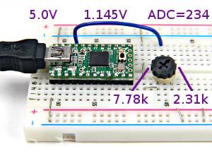
Vcc (Power Supply Voltage) Reference
Use this reference when your analog signal is created from the power supply. Reading the position of a trim pot is a good example.
 |
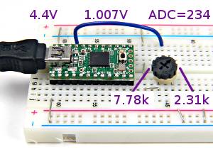 |
If the power supply voltage changes, so will your signal, but the ADC reference will also change the ADC's range to compensate, so you will continue to get correct results.
Resistive temperature sensors can be used this way, together with an accurate resistor.
Internal 2.56V Reference
The internal reference allows you to measure specific voltages, since it will remain at (approximately) 2.56 volts, even when the power supply voltage changes. The ADC input range will be 0 to 2.56 volts.Atmel only guarantees the internal will be between 2.4 to 2.8 volts, which is ±7.8% error. There is also no specification for it's stability over temperature changes. Often it will perform quite well, but there is no guarantee.
The internal reference is good enough for many basic applications. Often you can calibrate by measuring a known accurate voltage, and store the internal reference's actual voltage in your code or in EEPROM, then use it in calculations to correct for the error.
External Reference
When you need accurate voltage measurements, an external voltage reference chip is required. Because it affects the entire range of the ADC, the accuracy of your measurements depends on the accuracy of the voltage reference. Even inexpensive reference chips outperform the internal reference. For example, a LM385BLP-2.5 has ±1.5% initial accuracy (no calibration and adjustment), and a LT1009 has ±0.2%, both with very good stability over temperature changes.You can buy voltage reference chips in different voltages. 4.096 volts can be nice, because it gives a larger signal range, and each step of the ADC is exactly 4 mv. The external reference must be less than or equal to the power supply voltage.
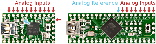
Configuring The Pins
The analog input pins can also be used as normal digital I/O pin. When a pin is used for analog input, it should be in input mode without the pullup resistor, so it doesn't interfere with the incoming analog signal. This is the default mode, so normally you don't need to do anything.However, analog signals can cause the digital input circuitry to consume extra power. The chip provides a way to disable the input circuits on the analog pins. This isn't necessary to make analog signals work, but it is nice to avoid wasting power, especially if running from a battery.
| Register | Bit 7 | Bit 6 | Bit 5 | Bit 4 | Bit 3 | Bit 2 | Bit 1 | Bit 0 |
|---|---|---|---|---|---|---|---|---|
| DIDR0 | Pin F7 | Pin F6 | Pin F5 | Pin F4 | Pin F3 | Pin F2 | Pin F1 | Pin F0 |
| DIDR2 | Pin B6 | Pin B5 | Pin B4 | Pin D7 | Pin D6 | Pin D4 |
Normally you would write to these registers near the beginning of your program, with a 1 in each bit corresponding to a pin where you have connected an analog signal. For example:
    DIDR0 = 0x13;   // Pins F4, F1, F0 have analog signals
    DIDR2 = 0x04;   // Pin B4 also has an analog signal
Sampling At Free Running Speed
Sometimes you may want to repeatedly measure a signal as fast as possible. Often it's important for every measurement to be taken at consistent time intervals, called "sampling". Fortunately, the ADC has auto triggering modes, where it will begin each conversion automatically. The default auto triggering mode begins each new conversion immediately after the prior one finishes.Because measurements are taken at high speed, usually an interrupt is needed to automatically read the result and store it into a buffer. Your program can perform other actions which may take longer than one ADC conversion time while the interrupt code takes care of reading the data. Later you can read the measurements from the buffer.
Download this auto trigger example code.
First, a buffer to store the samples is needed. This needs to be large enough to accomodate the longest delay your program may spend before it removes the data.
static volatile uint8_t head, tail;
static volatile int16_t buffer[BUFSIZE];
Unlike the simple example which accesses the ADC every time, with auto triggering you only need to configure the ADC once, and then it will operate on its own.
void adc_start(uint8_t mux, uint8_t aref)
{
    ADCSRA = (1<<ADEN) | ADC_PRESCALER;     // enable the ADC, interrupt disabled
    ADCSRB = (1<<ADHSM) | (mux & 0x20);
    ADMUX = aref | (mux & 0x1F);            // configure mux and ref
    head = 0;                               // clear the buffer
    tail = 0;                               // and then begin auto trigger mode
    ADCSRA = (1<<ADSC) | (1<<ADEN) | (1<<ADATE) | (1<<ADIE) | ADC_PRESCALER;
    sei();
}
Every time a measurement is made, the ADC will generate an interrupt. There are many ways you might choose to store the data. This example uses a circular buffer with a head and tail index.
ISR(ADC_vect)
{
    uint8_t h;
    int16_t val;

    val = ADC;                      // grab new reading from ADC
    h = head + 1;
    if (h >= BUFSIZE) h = 0;
    if (h != tail) {                // if the buffer isn't full
        buffer[h] = val;            // put new data into buffer
        head = h;
    }
}
When your program is ready to work with the data, it simply removes the data from the buffer. If you have spent substantial time doing other tasks, there may be many samples in the buffer.
int16_t adc_read(void)
{
    uint8_t h, t;
    int16_t val;

    do {
        h = head;
        t = tail;                   // wait for data in buffer
    } while (h == t);
    if (++t >= BUFSIZE) t = 0;
    val = buffer[t];                // remove 1 sample from buffer
    tail = t;
    return val;
}
Sampling At External Trigger
Instead of taking measurements at maximum speed, it can be useful to automatically take a measurement when some an occurs. In this example, the INT0 pin is used.

Download this external trigger example code.
Configuring the ADC is similar to free running mode above, but with a few small changes. ADCSRB gets addition bits to configure the automatic trigger mode. When writing to ADCSRA to enable the auto trigger mode and interrupt, the start conversion bit is not written. The first conversion will occur when INT0 changes. Finally, INT0 needs to be configured for the desired edge type.
void adc_start(uint8_t mux, uint8_t aref)
{
    ADCSRA = (1<<ADEN) | ADC_PRESCALER;     // enable the ADC, interrupt disabled
    ADCSRB = (1<<ADHSM) | (mux & 0x20) | ADC_TRIGGER_EXT_INT0;
    ADMUX = aref | (mux & 0x1F);            // configure mux and ref
    head = 0;                               // clear the buffer
    tail = 0;                               // and then begin auto trigger mode
    ADCSRA = (1<<ADEN) | (1<<ADATE) | (1<<ADIE) | ADC_PRESCALER;
    EICRA |= ((1<<ISC01) | (1<<ISC00));     // config ext INT0 rising edge
    sei();
}
The only other minor change required is clearing the INT0 flag. This is the same flag that would cause an INT0 interrupt, and would be cleared automatically by that interrupt. But the INT0 interrut is not actually enabled (the ADC interrupt is), so this bit needs to be cleared manually. Some interrupt flags, like INT0, are actually cleared by writing a 1 to them. Yes, it seems strange, but that's the way Atmel designed the chip, and documented it in the datasheet.
ISR(ADC_vect)
{
        uint8_t h;
        int16_t val;

        val = ADC;                      // grab new reading from ADC
        EIFR = 0x01;                    // clear INT0 flag
Events from timers can also be used to trigger the ADC. The process is similar, with manual clearing of the flag, and of course setup for the timer to create the events.