Tutorial 2: RGB LED
In this tutorial, you will connect a RGB (Red, Green, Blue) LED (Light Emitting Diode) to your Teensy. Because there are 3 different color LEDs inside, you can turn on different combinations to simulate many colors. By using more sophisticated programming, you can achieve very interesting color effects.Materials Required
- Teensy 4.0 with Pins
- Tutorial Parts Kit
- Solderless Breadboard
- USB Cable
- Wire Stripping Tool (#22 size)
- Computer with USB
Breadboard Usage
A solderless breadboard gives you a very quick and easy way to build circuitry. If you have used a breadboard before or are familiar with how it works, you can skip this section.Inside the breadboard, groups of holes are connected, so when you plug wires or components into holes from the same group, an electrical connection is made.
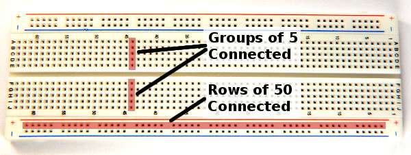
Most of the holes are in groups of 5. Usually you will connect components by plugging them into nearby groups of 5, and then add wires to connect those groups to others to complete your circuit.
Along the top and bottom of your breadboard are long groups which are usually used for power. Because many connections are made to the 2 power lines, it's very convenient to have them run the entire length of the breadboard.
How you arrange the wires is largely a matter of personal style. In these photos, power connections and most components are mounted with legs bent at 90 degree angles and trimmed short. Usually you don't change these, so spending a few extra moments to mount these close keeps them out of your way. Often longer run connections are changed, so leaving extra length makes experimenting easier.
The electricity does not care if you carefully measured a short wire or used a (reasonably) long wire. Use whatever style you like!
LED Wiring & Testing
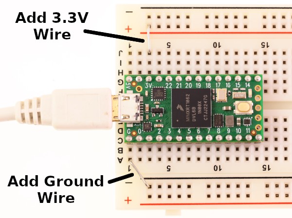
The first step is to add short wires to connect the long power rows to the 3.3 volt power provided by Teensy.
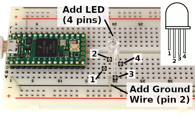
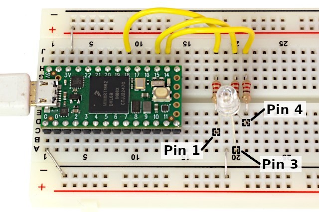
Next you will need to plug the RGB LED into your breadboard. There are 4 pins, where pin 1 is the shortest and located on the side with the flat edge.
You will need to spread the pins slightly so they fit into 4 separate groups of holes. Pin 2 needs to be connected to ground, so place a short wire between that hole group and the ground row.
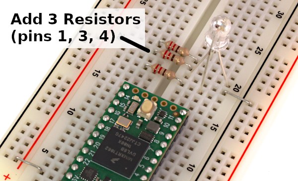
On each of the 3 positive pins, place a 220 ohm resistor (red, red, brown, gold).
Unlike a light bulb, the diode inside a LED will use as much power as it can. You must connect a resistor which will serve to limit the power. Never connect a LED directly to the power supply. Doing so would destroy the LED.
Now you are ready to test if the LED works. When possible, test your connections before you attempt to make them work from code in the Arduino software.
Simply touch a piece of wire between the resistor to the +3.3 volt power row. The LED should light!
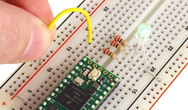
Repeat this test for the Blue and Red. Remember, do not touch the power directly to the LED. A resistor must always be connected between the power and LED.
Connect to Teensy Pins
With the LED ready, all that's left is connecting the 3 resistors to 3 pins on the Teensy. As you create electronic projects, a critical first step involves choosing which pins with which features to use. Fortunately with a solderless breadboard you can quickly change pins and experiment.
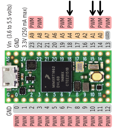
In this tutorial the PWM feature is used, so 3 pins with PWM are needed. Using the Teensy 4.0 board, pins 14, 15 and 18 have PWM and are close. Just plug in 3 wires to connect from the resistors to the pins.
Schematic Diagrams
Electronic circuits are documented using schematic diagrams. Here is a simple schematic for the connections you just made.
From this schematic, it is easy to see which color is connected to which pin. Schematics document the connections, without details of how the actual connections are made.
When you find information about how to connect more types of circuits to your Teensy, usually they will be expressed in schematic diagrams.
Using Digital Output
To start using the RGB LED, open the blink example, from the File > Examples > 01.Basics > Blink menu. Edit the code to use pin 14 by changing "LED_BUILTIN" to "14". Edit all 3 places where "LED_BUILTIN" appears. Then click Upload. You should see the LED blinking red.Before continuing, you should quickly repeat for the other 2 pins. If any wire is not connected, you can much more easily diagnose and fix the problem by testing each color individually.
The blink example contains 2 sections, a "setup" function that configures the pin using "pinMode", and a "loop" function which turns the pin HIGH and LOW. You can easily expand this program by copying these things 3 times, and change "ledPin" to a name for each separate pin.
int redPin =  14;
int greenPin =  18;
int bluePin =  15;

// The setup() method runs once, when the sketch starts

void setup()   {
  // initialize the digitals pin as an outputs
  pinMode(redPin, OUTPUT);
  pinMode(greenPin, OUTPUT);
  pinMode(bluePin, OUTPUT);
}

// the loop() method runs over and over again,

void loop()
{
  digitalWrite(redPin, HIGH);
  delay(500);
  digitalWrite(greenPin, HIGH);
  delay(500);
  digitalWrite(bluePin, HIGH);
  delay(500);
  digitalWrite(redPin, LOW);
  delay(500);
  digitalWrite(greenPin, LOW);
  delay(500);
  digitalWrite(bluePin, LOW);
  delay(500);
}
When you run this program, the LED will be red, then when the green LED turns on, you will see yellow, because red and green light combine to form yellow. When the blue pin is turned on, you should see white (perhaps with some color if the 3 LEDs and resistors are not perfectly matched). Then when the red turns off, you should see cyan, and when the green turns off, you should see blue. The pattern will keep repeating, because "loop" continues to run over and over.
You can experiment with turning on different combinations of colors and using different delay times. Some interesting patterns are possible, but to really achieve interesting colors and effects, you need more control than just turning each color completely on or completely off.
Using Analog (PWM) Output
The PWM pins have the ability to turn on at different intensity, from 0 (fully off) to 255 (fully on). PWM stands of Pulse Width Modulation, which means the pin is actually pulsing on and off very rapidly to make this happen, but the net effect is you can control the brightness of each color.To control the intensity, just use "analogWrite" in place of "digitalWrite". The second parameter should be a number between 0 to 255, instead of only "LOW" or "HIGH". Here is one example:
int redPin =  14;
int greenPin =  18;
int bluePin =  15;

void setup()   {
  pinMode(redPin, OUTPUT);
  pinMode(greenPin, OUTPUT);
  pinMode(bluePin, OUTPUT);
}

void loop()
{
  analogWrite(redPin, 30);
  delay(500);
  analogWrite(greenPin, 200);
  delay(500);
  analogWrite(bluePin, 40);
  delay(500);
  analogWrite(redPin, 150);
  delay(500);
  analogWrite(greenPin, 0);
  delay(500);
  analogWrite(bluePin, 250);
  delay(500);
}
With analogWrite you can create almost any color by changing the numbers!
Using Variables
Your program already contains 3 variables, "redPin", "greenPin", and "bluePin". These are assigned a number and never changed, because it would be senseless to change the number when the wire remains physically connected to the same pin.You can create more variables and change them as your program runs. Here is an example which uses a variable to fade the LED color slowly from green to red.
int redPin =  14;
int greenPin =  18;
int bluePin =  15;

void setup()   {
  pinMode(redPin, OUTPUT);
  pinMode(greenPin, OUTPUT);
  pinMode(bluePin, OUTPUT);
}

int redIntensity = 0;

void loop()
{
  // set all 3 pins to the desired intensity
  analogWrite(redPin, redIntensity);
  analogWrite(greenPin, 255 - redIntensity);
  analogWrite(bluePin, 0);

  // remain at this color, but not for very long
  delay(10);

  // increase the red
  redIntensity = redIntensity + 1;

  // since 255 is the maximum, set it back to 0
  // when it increments beyond 255
  if (redIntensity > 255) {
    redIntensity = 0;
  }
}
In the previous examples, every time "loop" ran, it did the same thing. But because the action now depends on a variable, each time "loop" runs it will create a different color. The delay is reduced to a very short time, so the loop runs 100 times per second. However, the color change is very small each time, so the LED smoothly fades from green to red.
In the analogWrite to the green pin, the red intensity is subtracted from 255, so when red is off, green is on, and as red increases, green will decrease. Each time the loop runs, "redIntensity" increases.
Near the end of loop is an "if" condition. This causes the following code between the curly braces to only run if the condition is true. When "redIntensity" becomes too large, it is set back to 0. The next time the loop runs, the LED will instantly go back to green. When "redIntensity" is not greater than 255, the code is not run, so it is not set back to zero.
You can create as many variables as you like (within the memory capacity of the chip) and use them in almost any way to achieve different color effects.
Now that you can create output to the pins, you are ready for Tutorial 3 to receive input signals.