|
|
| ||
|
Shopping Cart
|
| Home | Products | Teensy | Blog | Forum |
|
You are here:
8051 Tools
|
|
|
Using the 82C55 I/O ChipsMost of the I/O lines on the 8051 development board are provided by two 82C55 programmable peripherial I/O chips. This page provides detailed instructions and examples for using these I/O chips in your application. Before reading these examples, the simple LED blink examples should be read.
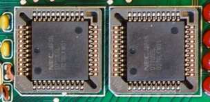
The chips shown in figure 1 are NEC UPD71055L. Despite the strange part number, these are NEC's version of the 82C55 chip. They are labeled D71055L on the top of each chip. Memory Mapped Peripheral AccessBoth 82C55 chips are external memory mapped peripherals. This means you must access them using certain memory locations using the MOVX instruction. Each chip has byte-wide registers that you access. These definitions allow your code to access the 82C55 chips.
Since the 82C55 chips are connected to the exteral memory bus, they must be accessed using the MOVX instruction. The MOVX instruction always uses DPTR to specify the memory location, and data is always transfered to/from the accumulator. Here is an example of how the 82C55 registers are accessed using assembly language:
When programming in C, the compiler takes care of handling the registers, so all you need to do is read the 82C55 registers as if they were ordinary global variables. Here is a simple example, equivilant to the assembly code above (the compile may generate slightly different assembly code):
Using SDCC, the variable declaration gives the compiler all the information it needed to "know" how to access the 82C55 chip. The "volatile" keyword tells the compiler's optimizer to always access the chip as shown. The "xdata" keyword tells the compiler that the access is the external data bus. The special syntax "at 0xF800" tells the compiler that the variable is located in memory at 0xF800 (by default, the linker would choose a location). And, of course, the variable is an unsigned char, so it will be accessed as a single byte. The 8 definitions above will simply work with the 82C55 chips, but understanding the definitions is necessary if you need to create them for additional custom hardware. Simple Input/Output (Mode 0) ConfigurationBefore you can access the 6 registers corresponding to the I/O pins, you must configure the 82C55 chips. Luckily, all you need to do to configure each chip is write a single byte to its configuration register. Here is a table with all of the commonly used configuration bytes:
Each chip requires its own configuration byte, so the process for configuring ports D, E (leds) and F is the same. When the system is reset, the 82C55 chips default to all inputs (configuration byte 0x9B). When configuring the 82C55 chips immediately following a system reset, a delay should be added. The reset signal is generated by a resistor and capacitor, and as the voltage falls, the 8051 will often begin executing code before the 82C55 reset pin detects the voltage change (it tends to "see" the high to low transition at a lower voltage). So a simple software delay before configuring the 82C55 chip should be used to allow time for the 82C55 to begin operating. The 82C55 will ignore the write to its configuration register if it is still in reset mode. Once you have written the configuration byte, the three ports may be accessed simply by reading or writing their registers. Port C (or port E on the second 82C55 chip) may be configured where half of the pins are input and the other half output. In that case, 82C55 chip ignores the unneeded 4 bytes when you write to port C, and when you read port C, the undefined 4 bits should be ignored. You may change the 82C55 configuration at any time by writing a new configuration byte. Doing this effectively resets the 82C55 chip. All pins defined as outputs by the new configuration byte are cleared to zero. This should be considered when designing hardware that interfaces to 82C55 pins in an applicaton where the configuration will be changed, rather than simply programmed once at startup. The output pins default to low immediately after the configuration byte is written to the 82C55.
TODO: explain the complex modes TODO: single bit writes to port C
TODO: example code (any suggestions ??)
| |||||||||||||||||||||||||||||||||||||||||||||||||||||||||||||||||||||||||||||||||||||||||||||||||||||||||||||||||||||