|
|
| ||
|
Shopping Cart
|
| Home | Products | Teensy | Blog | Forum |
|
You are here:
8051 Tools
|
|
Reset and Crystal Oscillator TestsFor the processor to boot up and run code, it must have clock signal from the crystal, and a reset pulse. These are rarely a problem and these are tested on all boards assembled by PJRC. However, if your board does not respond, these are easy to check.Reset SignalThe 87C52 uses an "active high" reset signal. This means the 87C52 does not execute code when the reset signal is high, and it begins running code when this signal goes from high to low.
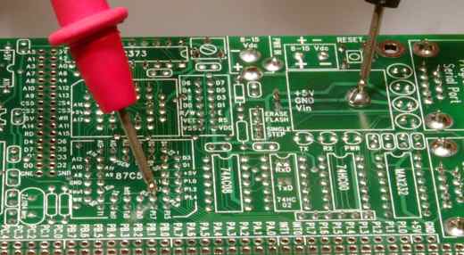
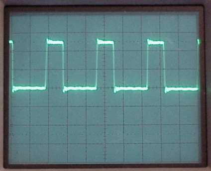
The reset signal can be verified by measuring the voltage on the RST pin of the 87C52, as shown in Figure 1. This is much easier if an aligator clip is used to secure the negative lead to the screw mounting the 87C52, so one hand is free to press the reset button. When the reset button is pressed, the RST pin should measure 5 volts DC. When the button is released, it should go back to zero. The resistor-capacitor circuit that creates an initial reset pulse on startup can be "seen" on multimeters with a faster response time. Usually the multimeter's auto-ranging feature must be disabled. The voltage makes a transition from 5 to 0 volts with a time constant of 0.1 seconds. Most multimeters will display 1, 2 or 3 readings between 5 to 0 volts just after the button is released. Crystal OscillatorTo execute code, the 87C52 requires a stable clock from the crystal oscillator. The crystal oscillator should not be measured directly, because the capacitance of multimeter leads can change the frequency or in some cases cause the oscillation to stop.The easiest way to verify the clock is by observing the ALE signal. When the 87C52 is clocked correctly, this pin outputs a square wave at 3.6864 MHz with a 33% duty cycle. It is a digital output with drive sufficient to be measured directly. Most multimeters can not make AC or frequency measurements at this high frequency. However, the DC voltage measurement will show the average voltage. If you measure 1.67 volts DC on the ALE pin, the crystal osciallator is probably working. TODO: what happened to that photos for figure 2, showing lead on ALE. If you have an oscilloscope, you can measure the ALE signal. You should see the waveform shown in figure 3.
|