|
|
| ||
|
Shopping Cart
|
| Home | Products | Teensy | Blog | Forum |
|
You are here:
8051 Tools
|
|
|
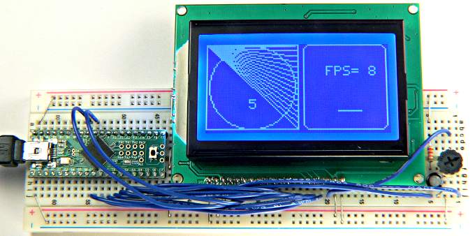
128x64 Graphical LCDUpdate: This 128x64 Graphics LCD can be used with Teensy 2.0 and Teensy++ 2.0, using this library code and Teensyduino.
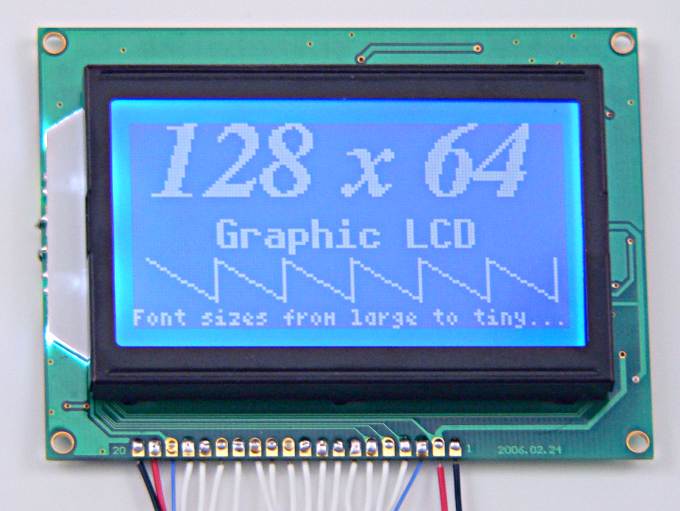
The above image was created using this code:
        lcd_init();			// init the LCD, clear the buffer
        print_to_lcd = 1;		// printf_fast to LCD buffer
        buf_set_font(font_timBI24);
        buf_set_position(6, 0);
        printf_fast("128 x 64");	// first line: 128 x 64
        buf_set_font(font_7x13B);
        buf_set_position(25, 30);
        printf_fast("Graphic LCD");	// second line: Graphic LCD
        buf_set_font(font_4x6);
        buf_set_position(0, 58);
        printf_fast("Font sizes from large to tiny...");
        for (i=4; i<120; i+=20) {
                buf_line(i, 42, i+20,  55);	// diagonal line
                buf_line(i+20, 42, i+20,  55);	// vertical line
        }
        lcd_update();			// copy buffer to LCD
Example Code (for 8051 processors)Example code (beta test version):lcd_128x64_07.tar.gz lcd_128x64_06.tar.gz
Fonts (beta test):
Diagnostic Utility: Accessing The LCD (lcd_driver.c)Only two simple functions access the LCD hardware.
lcd_init()
lcd_update() Off-Screen Buffer Operations (lcd_buffer.c)To actually use the LCD, you need to compose the image in the off-screen buffer using these functions, then call lcd_update() to display it.
buf_set_position(x, y)
buf_set_font(font)
buf_putchar(ch)
buf_draw(shape_ptr)
buf_pixel(x, y)
buf_line(x1, y1, x2, y2)
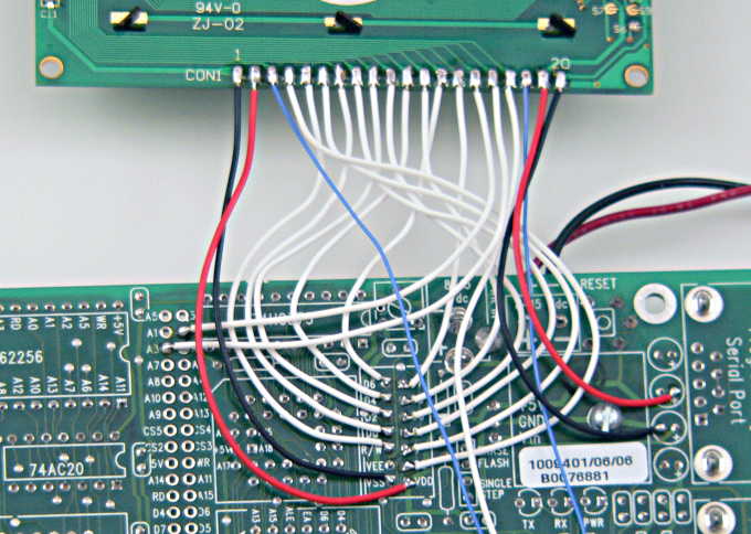
buf_clear() Connections To 8051 Board
How to connect to the 8051 board:

LCD             8051    Notes:
---             ----    -----
 1: Vss         Ground  (pin 1 on LCD connector)
 2: Vdd         +5V     (pin 2 on LCD connector)
 3: Vo                  Connect to 5K POT wiper
 4: D/I         A1      (pin 4 on LCD connector)
 5: R/W         A0      (pin 5 on LCD connector)
 6: E           E       (pin 6 on LCD connector)
 7: D0          D0      (pin 7 on LCD connector)
 8: D1          D1      (pin 8 on LCD connector)
 9: D2          D2      (pin 9 on LCD connector)
10: D3          D3      (pin 10 on LCD connector)
11: D4          D4      (pin 11 on LCD connector)
12: D5          D5      (pin 12 on LCD connector)
13: D6          D6      (pin 13 on LCD connector)
14: D7          D7      (pin 14 on LCD connector)
15: CS1         A2
16: CS2         A3
17: Reset               10uF cap to ground, 22K resistor to +5V (see schematic)
18: Vee                 Connect to POT side (other side to ground)
19: A           +5V
20: K           Ground
As an alternative to using a 5K pot for the contrast adjust, you can use higher impedance values with a PNP transistor. A 2N3906 or almost any other small general purpose PNP transistor should work, allowing any pot value between 10K to 250K. Update: Pin 17 can be connected directly to +5 volts. The 22K resistor and 10µF capacitor are not necessary. Extensive testing has shown this LCD works fine without a pulse on its reset line. |