|
|
| ||
|
Shopping Cart
|
| Home | Products | Teensy | Blog | Forum |
|
You are here:
MP3 Player
|
|
|
HistoryDecember 28, 2001: I have (finally) set up aDecember 17, 2001: It's official, firmware release 0.6.4. It's been quite some time since the last release and a lot has changed. This code should be much more stable than all the previous 0.6.x versions. I also added some minor features back to the old non-SIMM version (now 0.1.3), so it's auto-detect IDE master/slave and will work with those older buggy drives. Please give 0.6.4 a try. Your feedback, tested with your hard drive and your SIMM, would really help. As usual, I'm behind on answering emails. Now that this firmware release is out, I'll try to catch up tonight and tommorrow. December 14, 2001: I did more work in the firmware and FPGA over the last couple days, and it is now committed to CVS. Dave's snapshot page should have it soon. Here's a compiled image with all these changes.
The other interesting thing that happened today was a discussion on the SDCC developer mail list (which I am involved with). SDCC generates very inefficient code for initializing static and global variables. It's looking like this will improve soon. December 12, 2001: Last night I worked yet again on the DRAM controller, this time on the 8051-interface section. I redesigned the address latching circuitry (using the 8051's ALE to enable flip-flops instead of using it as a clock). This appears to greatly improve the stability of the player. My test board has been running for a little over 11 hours continuously since I made this change. These "hardware" changes are inside the FPGA, so your board will get these changes when you upgrade the firmware. No physical changes are made to the board, and the changes will work on all three board revisions. I committed this new DRAM controller to the CVS server this morning, so Dave's nightly build page should have a compiled image with the new DRAM controller sometime tommorrow. (I'll put a copy on the yahoo group so you can get it now). Please give this new code a try and let me know if it is stable or crashes on your board. It's still too early to tell for sure, but it's looking pretty good. The board I'm using now is the worst one I have... it's never managed to run any of the 0.6.x firmware for more than a 4-5 hours, and with this new code it's been playing without problems since I made the change 11 hours ago. Tom also committed a large group of cleanups and improvements to the code, mostly in the display and non-volatile parameter handling. There will probably be some more fixes over the next couple days. I am particularly interested in integrating Dave Johnson's idea to allow full max volume output while still having the tone controls. If things are looking stable, I'll make an official release (probably 0.6.5) sometime during the weekend. If you've been following the yahoo group discussions, you've probably seen talk about officially ending the display beta test. The display firmware seems to be very stable. The display bugs appear to have been completely solved by the changes I committed on August 8th. Tom added several new features to the display board's firmware in August and September. The last bug was fixed on October 7, and there have not been any changes since. All displays that have been shipped in November and December have the latest firmware and do not need an upgrade. Robin and I are planning to send free display upgrade chips to everyone who has the original display firmware. This upgrade will fix the shift-by-two-pixels bug and other minor pixel corruption, and it'll also update the display with all of Tom's performance enchancing code, which greatly reduces the flicker when the screen is redrawn and reduces the bandwidth used on the serial port. I'll post details when we're ready to send the chips. We're planning to have a special page with a form to request the chip (since many people's addresses may have changed). PJRC will pay for the chip and shipping via low-cost postal mail for everyone who has the old firmware. December 11, 2001: Today I spent quite a bit of time investigating some bugs reported by "Marco", who apparantly is attempting to add cdrom support to the code. He ran into all sorts of strange (and fairly reproducable) problems. He didn't send a copy of his code, but after a while I managed to reproduce the problem and ultimately get to the bottom of it. I was hoping this might lead to a fix for the current bug that causes the firmware to crash after some time, but Marco's problems turned out to be related to some tricky aspects to using 16 bit PIO access to the IDE interface. The current firmware only uses PIO access as startup. I added some description of the 16 bit PIO issues to the memory map page. December 10, 2001: It looks like subscribers are started receiving the January issue of Poptronics, which includes an article about this MP3 player project. The article shows the rev A board, as the new rev C board was not ready in time for their publication deadlines, and rev B wasn't documented well enough for the article. All three revisions to the board have made improvements to the power supply, while the MP3 player part has remained the same. If you're a Poptronics reader and you plan to build this project, please use the newer rev C design, which makes some significant improvements to the power supply section. Rev C printed circuit board artwork and assembly instructions are on-line. Saddly, I have not had time to draw a nice schematic for the new rev C board, but I do have a hand-drawn schematic of the new power supply section, so I'll get that scanned soon and put it on-line (and eventually draw a nice schematic like the other ones). If, for some reason, you really want to build rev A, don't forget to check the Rev A Errata page. The Poptronics article probably doesn't mention these errata items, which is entirely my fault. November 4, 2001: This weekend PJRC.COM moved to new hosting at Verio. The new server has a lot of bandwidth, so pages should load much faster for anyone with DSL, cable or other fast internet access. Dial-up users may even notice an improvement at busy times. Hopefully the days of DSL users bringing the site to its knees with Teleport Pro will soon be a distant memory. Verio should also be much more reliable that our old ISP (inetarena.com), who's had many outages and performance problems since its founder sold the company to netrover.com. The DNS was switched Saturday afternoon, and since then the new server has slowly been taking more of the traffic. A few people are still accessing the old server. If you're seeing this message, your nameserver has updated with the new IP number and you're accessing the new server. Our email was down for part of Friday and Saturday, so if you sent Robin or me a message and it bounced, the email should be working again. CVS is still not loaded on the new server, but it should be running sometime tommorrow. I'm hoping to wrap up all this server transition stuff Monday night and spend the rest of the week working on much-needed updates to many of the web pages. Moving the entire website and getting everything to work again has been quite a bit of work over the last few days. It's quite possible I missed something. If you notice anything broken, please send me an email. We have several more assembled boards and unassembled kits available. We actually ran out of kits in the middle of last week and the last assembled board from the first batch was shipped on Friday. The good news is that we've got several more in stock just in time! October 29, 2001: We've finally cleared all the backorders for mp3 player boards and kits. There's actually a few rev C boards and one kit left at the moment, and we're no longer reserving them for people who selected Western Union or PayPal but haven't responded to emails over the last week. It feels great to finally be caught up! We'll have the next batch of boards ready on Nov 5, so if we run out this week it'll only be until next Monday. This weekend I created the Rev C kit assembly diagrams. At the bottom of those pages is a download for a hi-res copy of all 12 assembly diagrams, which looks good when printed on a laser printer. This time, I put some extra work into getting all the parts very clearly labeled with bold text and all the other parts nicely gray'd out to make it easier to read, even when printed without color. If you're one of the people who's recently received a Rev C kit, please contact me if anything is unclear in these diagrams. Robin and I both double checked them, but it is always possible I could have made an error or omission. The Rev C layout artwork is also on-line. I'm still working to update the schematic for Rev C, and hopefully it will appear sometime this week. I also have the images ready for a schematic and layout of the pushbutton adaptor board that comes with the display. I know several people have requested this... it will be up very soon. I'm trying to fill in the missing web pages (here and on other parts of the web site) over the next several days. Once these are written/drawn, I'm planning to get back into working on the firmware in a serious way. We've been in contact with Gernsback Publications very recently, and it looks like they will run a story about this little mp3 player project in the January issue of Poptronics Magazine (formerly Popular Electronics). The material in the magazine will cover the Rev A board, since we didn't have all the info needed for Rev C in time for their deadline. The story in the magazine won't have much that isn't already here on the web site, but it should be able to reach a lot of folks who don't know about the site. I'm told that the January issue hits the news stands on December 11, a couple weeks before Christmas. If you want a copy, that'd be a good time to look for it. I'm told that the mp3 player will appear alongside some antenna project on the cover of the magazine. We sent them a board to take photos, but I do not know exactly what they will do. We are planning to increase the price of the unassembled kit and the display, but only slightly. Don't panic... nothing has changed yet, and nothing will change until at least November 15 to allow anyone who's "thinking about it" to order at today's prices. The unassembled kit will go to $150, which is the same price as the assembled and tested board. The main reason for this is because we spend a similar amount of time putting the parts into the nicely labeled bags as we do putting them into the circuit board, but the tech support on kits is much harder. On the display, we're going to increase to $42 (adding only $5). This is my fault... I underestimated the cost of building the custom cables, particularily the ribbon cable that needs to be hand soldered on all 17 conductors. All the other parts will remain the same price, at least for the forseeable future. Well, that's a bunch of things for one news update. I think that more or less covers everything. Now that we're finally caught up on these mp3 players and the 8051 development board, I'll be doing some much-needed updates to the web site and then quite a bit of work on the firmware. October 21, 2001: We finally have the first small batch of Rev C boards and kits ready. Here is the photo of the first Rev C board:
 Here is a larger photo (120k). We'll be shipping boards and kits tommorrow, and this first small batch should cover most, if not all of the backorders. I'll be posting info about the new rev C to the technical docs section over the next week, but for now Robin and I are tired and need to take a little break! October 10, 2001: Well, I've missed the deadline to get the first 20 rev C boards made by Saturday (Oct 13), but it looks very good for getting them sometime next week. One really positive thing that's come out of this long process is that I've finally drawn a reasonable schematic for the first board. Well, it's missing the pushbuttons and serial interface, but that'll be easy to add. Getting all those connections checked was a lot of work, as you can see from that image. I know there's a good number of people (several are students) who've been waiting for the schematic for quite a while, so enjoy. Rev C makes only a couple minor tweaks to the main schematic, so it'll be relatively easy to get a complete rev C schematic up by the time we're shipping boards. Also, I should mention that I've fallen behind in answering emails (worse that usual...) Please be patient, I will try to answer them all, probably next week while the boards are getting fabricated and we're making the inevitable last-minute orders for a few missing parts. October 4, 2001: It probably seems like I've dropped off the face of the earth... no updates to this page, not much happening with the firmware lately, ran out of mp3 player circuit boards, etc. Well, here's a bit about what's been going on lately. We ran out of boards about 5-6 weeks ago, and once more I was faced with the decision, "should I just make more of the exact same board, or should I try to improve the design". As you may know, I've never been 100% happy with the power supply part of the board. Rev A worked, though not nearly as efficiently as I wanted. Rev A also has a 4.5 to 6 volt input, and it was easy to damage the board by applying more than 7 volts to this input. I made some minor changes to create rev B with a sturdy 6 to 10 volt input (in addition to the 10-15 volt input), and the change reduced the heating in the TIP102 transistor. Still, it seem like it ought to be possible to do better. Well, it isn't easy. Over the last several weeks I've made multiple attempts that turned out to be dismal failures at a better power supply. I was about to give up. I took one more shot at it, and finally a result that I think is pretty good has come about. Here's a photo of the prototype:
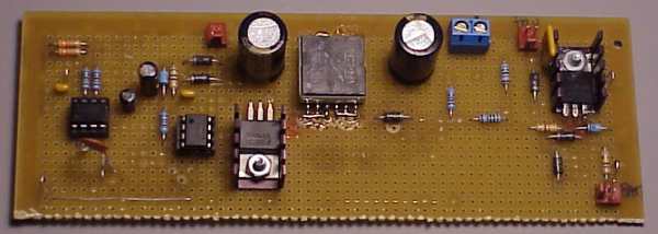 This supply uses a lot of the same parts as rev B, but the performance is considerably improved. The higher voltage input is still 10 to 15 volts, with protection from the nasty spikes from a car's alternator. The low voltage input is now 4 to 10 volts, which means rev C will be able to run from four AA batteries like rev A, but will be sturdy like rev B. Rev C's battery input will be much more efficient that either rev A or rev B... I wanted to be close to 100% efficient, but that's nearly impossible for a supply that can step up or step down as needed. I made many attempts to get really high efficiency, some using lots of expensive parts, but in the end none worked really well. I talked with a guy who's an expert at switching power supplies, but all his ideas revolved around complex custom transformers and inductors. I tried contacting some of the companies that make these. Most won't touch it for under 5000 parts/year, and those that will are very expensive for qty 100-200. So it looks like the standard parts (Cooper/Coiltronics) will have to do. I think this rev C supply is a good compromise and it keeps the cost and total size about the same as rev B. One of the major changes is a new PWM control chip. This new part (TL5001) includes a sort start limiter, which will eliminate the problem were the board can trip the current limiting that's built into many lab bench power supplies (not an issue for batteries and "wall warts"). The new switching supply makes only +5 volts, and a LP2950 linear regulator makes the 3.3 volts. Creating only +5 volts allows the supply to make better use of the transformer, and I switched to a somewhat smaller transformer (less magnetic material = lower losses is the core, which more than makes up for the small loss in the LP2950 for 3.3 volts). I also did a little trick to use the flyback voltage to create a little higher drive voltage for the mosfet, which really helps reduce the heating in the mosfet (and improve efficiency) when the supply is run from only 4 volts. There's also an undervoltage lock-out and a max duty cycle limiter so that the supply acts much more gracefully as the battery voltage falls below 4 volts. I also overhauled the circuit that muxes the 12 volt and battery inputs and protect from car alternator noise while preventing the battery from seeing destructive overcharging. The rev A and rev B versions used a diode in series with the battery, which really cuts into the battery's run time. The rev C design uses a P-channel mosfet (it's on the bottom of the prototype board) to eliminate the loss from that diode. I think that's most of the changes... all in all, it's quite an improvement over rev A and rev B. Though not as ambitious as my first couple (failed) attempts, I think it's pretty good and it'll fit into the existing board size without changing the cost of the board much (we'll keep the price the same at $150). A major frustration in this project has been the CAD software. The program I used for rev A and rev B is having a lot of trouble (corrupted files, bogus gerber output, etc). It really sucks to have to redraw an entire board with this many connections, but that's exactly what I had to do. Luckily I have access to some better software now, which has its own set of minor problems, but at least it seems to have a solid database and file format behind it. I'm going to avoid mentioning names, but I will say that the really problematic program was one of the really inexpensive packages. I guess you get what you pay for... So the big question is when will these rev C board be available. I wish I had an exact date. Today the new transformers finally arrived. We're still missing some of the important parts, but have a small number of them left over from rev B. I talked with the board fab company and they can get us a small number of boards in a hurry (for an extra fee, of course). We're going to try to get the first rev C boards and kits shipped on Oct 15. I know we have a few folks waiting who're using the board as part of a project with an urgent deadline. We're going to try to ship to them and the people who've been waiting more than 2 weeks. We'll get the rest of the boards and have them built later in the month... so hopefully we can have all the backlog taken care of before Halloween (Oct 31). I probably won't manage to get much done on the firmware until the boards and kits are sitting in stock and all the orders are shipped. One exception to this is the display beta test. Tom did a lot of work on the display firmware a couple months ago, and I made some small changes to fix the 2-pixel-shift bug and other random drawing bugs. Tom's new code includes some changes to make the display update better with less communication bandwidth from the player, but there's one more bug in this new code that prevents it from really improving the redraw responsiveness. Tom has been on a vacation for a couple weeks but recently returned. He'll probably look into this soon, and either way I'll do some work with the display firmware so that when we have the board again later this month, we'll have displays with the new debugged and improved code on them (the display is not easily upgradable like the player is). So that's more or less where the project is at. I am alive and well, but quite busy trying to get everything put together to finally have rev C boards available. Hopefully next month we'll have plenty of boards again and I can get back to working on the firmware and doing much-needed updates to the web site. August 24, 2001: It's been a few weeks since I've added any updates here. I'm going to try to get an update up here at least once a week. It's been almost exactly 2 months since the firmware development was moved to CVS, and during that time several people have come on board and really helped fill out a lot of the player's features. Ian did quite a bit of work to add items to the display, including interactive tone controls. Zach added code that scans all the directories on the drive. I overhauled the device drivers to speed this up, and Matthew has done quite a bit of work to optimize this. He also began some of the initial coding to be able to read .m3u files, but much remains to be done there. Matthew also made several valliant attempts to make that code non-recursive (allowing almost limitless subdirectory depth to be scanned), but that's a difficult task. I did some optimizing and improved the recursive version, so we can at least scan 5-6 levels deep. Somewhere in there I spent a very frustrating week or so chasing after the bug that makes the player lock up eventually, but it still ellludes me. Early on, Ian had written some code to find ID3 tags. I fixed a couple bugs, and then Ian, Chris, Matthew and others did quite a lot with ID3 tags, and today's firmware displays the ID3 info on the LCD. Zac joined the group and fixed a long-standing bug in my I2C driver code. Zac then added an nice elapsed time display, where "--:--" had always been, and he did some cleanups and improvements to the ID3 parsing code. Matthew did some more work to try to process .m3u playlist files, but this really needs more support from the drivers. I added a driver function to allow memory mapping 4k sections files, but more library-level support is needed for parsing before .m3u processing can happen in a reasonable efficient manner. Chris added more play modes, sequential in just one directory or the whole drive, random in directory or whole drive, etc. Chris also added a resume feature, where the player will usually remember where it was in the list and start there again when it is used again after a shutdown. Tom has been working on adding some cool features to the display board code. I did some testing and fixed the shift-by-two-pixels bug in the display, and Tom has added a freeze/unfreeze feature that should make updates flicker less. Tom also put in support for scrolling directly in the display, which will cut down on the excessive data trasfer to the display. I believe this is most of what's happened in the last month, but it's hard to recall everything in detail... If I've missed something that anyone contributed, please let me know. So what's next? Well, it's becoming clear that soon there needs to be a new official firmware rev, even if we can't call it "stable". In firmware development, probably the next major thing will be an overhaul of the main playback state machine. This is no small task. Eventually this would enable playing files larger than the SIMM, and probably also use the avaialble memory better, perhaps to read ahead into the next file if there is a lot of memory, perhaps to read the first part of many upcoming and/or previous files to have rapid response to the pushbuttons. There's also the task of reading .m3u playlists, ID3v2 tags, fast forward/rewind, more LCD stuff... the list goes on and on. Actually, there is a file in the firmware source called "wish_list.txt" which is more or less the official list of requested features. This list is writable only to developers with CVS commit access, mainly so that ideas are filtered through developers who have an idea of what is and isn't feasible. All developers are welcome to add to the list (or remove as things are implemented). On the less technical front, we ran out of circuit boards a few days ago. We're working to get more made, but it will be a couple weeks. It'll also consume some of my time, so I won't be doing as much work on the firmware until they're done. The final thing that's going on it pjrc.com will be moving to a different ISP. There will be a couple weeks of overlap, so with some luck things will go smoothly with the DNS and there won't be any down-time (I hope). The new server will be at a data center with very high speed connections to the net, so viewing pjrc.com should become noticably faster if you have a broadband internet service. It should also be much more reliable that what we've been using. August 5, 2001: Today I spent the whole day writing a dir_read_fast function which is an attempt to make a much faster directory read. If you've tried 0.6.3.3 or the recent CVS versions, you know that they scan all the subdirectories on the drive (up to some level, currently 3 deep in today's CVS code). Today this is slow. This new fast directory read should make a big difference. Right now it's very new and not used by the directory scanning code (it's API is a bit different). Also, if you haven't been keeping up with the latest CVS code, about a week ago Matthew and Ian got ID3 tag display working. All of the 8 lines of the display now do something. I want to make an official release on the firmware page, but it will have to wait as I spent the entire day doing the new fast directory reading code. July 25, 2001: Quite a bit has happened in the last 24 hours! I haven't had much time to work on the project for the last few weeks, and the firmware hit a limit called DSEG overflow which prevented anyone from doing much. A couple days ago I wrote a perl script that checks the DSEG usage and I made a bunch of small improvements to make more DSEG space. Matthew added display of which directory is being played. Ian committed some bug fixes. Quite some time ago Ian wrote code to read the ID3 tag, but until last night it wasn't finding the correct place in the file. I fixed that, and then Matthew picked it up and added parsing and display of the ID3 tag info (title, album, artist). There's been some fiddling with optimizing the directory scanning code, and it was broken for a while but looks like it may be fixed now. Things are really moving. If you want to try out this cool new stuff, grab the source code from CVS, or download from Jim's automatically updated compiled images. If there aren't any major bugs, I'll make rev 0.6.3.4 over the weekend. June 30, 2001: Zach added code that plays all the MP3 files on the drive, not just the root directory! Ian added adjustment of the bass and treble roll-off frequencies. I've been quite busy lately had haven't even been able to keep up with my email and the yahoo group. Today I included Zach's new code. I probably won't have much time for this project until July 4. If you've sent me an email and I haven't answered, please try to wait until the 4th to remind me. June 26, 2001: I stayed up late and did some investigation into why some newer SIMMs are incompatible with the player. The short story is that there is both good news and bad news. First, the good news is it looks like I'll be able to improve the SIMM detection code to make these newer SIMMs work properly. But, the bad news is that the hardware was designed around the older style of SIMM and only a portion of newer SIMMs will be usable with the player. Here are some photos of both types of SIMMs. I have an archived copy of the datasheet for the older SIMM type. When I designed the board, this was the only datasheet I could find on-line. The four chips on that newer SIMM shown below are Samsung KM48C8000, and I was able to find someone's old copy of the datasheet (google is great!). Using the datasheet for the chips and some reverse engineering with an ohm meter, I was able to learn a bit about these newer SIMMs. Using today's firmware (0.6.3.2), this newer 32 meg SIMM is detected as 8 megs, and the player attempts to use it and crashes (because only 4 megs is actually usable).
The devil is in the details, and I'll describe what's going on a bit. 72 pin SIMMs have a 32 bit data bus. The bus on the player is only 16 bits, so the board connects the upper and lower 16 bits together and then tries to tell the SIMM to only read/write 16 bits at a time. SIMMs have four row control lines, four column control lines, and between 10 to 13 address pins. DRAM memory is arranged in a matrix. Other easy-to-use memories like SRAM and EPROM are also built this way, but you can't "see" the arrangement because there is some nice circuitry inside that takes care of those details. With DRAM, you have to deal with the arrangement of the matrix inside. This is where the row and column lines come into play. To access a particular memory location in a single DRAM chip, you have to specify the address in two parts. First, you drive the address pins with the number of the row you want and assert the row control pin. A short time later (68 ns on this board), you drive the address pins with the column you want and assert the column control signal. There's also a write enable bit. If it's high when the column control was asserted, the DRAM sends data to the player, and if was low it stores whatever data the player drove onto its data pins. This sequence of events to access the DRAM is done automatically every time the processor reads or writes the memory and also when one of the DMA channels needs to read. There is also another type of operation called refresh, which happens every 15.6 µs. When multiple DRAM chips are assembled together on a SIMM, there are several of these row and column control lines that are brought out to the pins of the SIMM, and therein lies a good portion of the issue at hand. To be specific, there are four row control lines, labeled RAS0, RAS1, RAS2 and RAS3, and four control lines labeled CAS0, CAS1, CAS2, and CAS3. On the 32 meg SIMM, each RAS line controls 4 megabytes that occupies 16 bits of the data bus, and for each 4 meg RAS-controlled section, two CAS lines control each half to allow 8 bit wide access. If that last sentence was confusing, here's a nice diagram (which might be even more confusing :)
 The mp3 player board uses the four RAS lines to enable one of the four 16-bit wide sections. It always asserts all four CAS lines at the same time (I ran out of FPGA pins and the chips that didn't get RAS asserted will ignore it). Using address pins A0 to A10 (as shown in the diagram) twice (row and column), there are effectively 22 address bits sent to the SIMM. Two of the address bits from the processor (or DMA) determine which of the four RAS lines gets used, for a total of 24 address bits. That's 16 million, and because two bytes are transfered at once, it all adds up to 32 megs of usable space and works quite nicely. Well, that's the way is was. Somewhere, somebody changed the way SIMMs were made, and many newer SIMMs are connected in a very different way than that diagram shown above. I don't have a similar diagram for the newer SIMM, because I haven't found any datasheets on these newer SIMMs and I didn't draw a diagram (special thanks to Micron, by the way, for that nice diagram and at least keeping their data sheets on line... without Micron I would never have been able to figure out how to do this project!) The newer SIMM uses only RAS0, and RAS0 controlls all 32 bits (instead of just 16 like the older SIMM). RAS1, RAS2 and RAS3 are not connected to anything at all! Worse yet, it uses 13 address lines instead of 11, where all 13 lines are used during the row selection but only 10 are used to select the column. The other three lines do nothing during column selection, but they are needed for the row. The sad truth is that the mp3 player board has 11 address lines, not 13 (there are no more pins available on the FPGA). It has 4 row select lines, and three of them are useless of this type of SIMM. There is only a single column select line that is connected to all four CAS signals, so when the player writes to the SIMM, it will actually be storing 16 bits of data into both the upper and lower 16 bits of the SIMM. Using only one RAS line, 11 bits during the row select and 10 bits during the column select, there's only 21 effective bits of address info, which gives 2 million 16-bit wide memory locations, or 4 megs. It's unfortunate that there's 32 megs of memory on there, but due to the board design and the SIMM's arrangesment, only 4 megs is usable. Of course, today the firmware incorrectly concludes that it can use 8 and then crashes, but at least that can be upgraded to check more carefully which parts of the 32 meg address spaces it can "see". Frustrating, but I guess it's better to know what's going on and at least be able to do something rather than have the code end up completely incompatible with these SIMMs. There appear to be many other arrangements on the newer SIMMs. For example, if this board were populated with KMC48C8100 chips (instead of KMC48C8000), it would still be a 32 meg SIMM, but 8 megs would be usable instead of 4 megs. On a simm like this, it possible to disconnect the RAS pin from two of the chips and connect them to RAS2 on the simm's edge to double the amount of memory the player can use, but there's nothing that can be done about the extra row address lines. If you're shopping for a 32 meg SIMM to use with this board, be sure to look for the older style, which almost always has 16 or 18 chips (8 or 9 per side), where each chip has 24 pins in four groups of six. The older 8 meg SIMM look similar, but the chips are 20 pins in four groups of five. June 26, 2001: I just posted a new firmware rev... the first one made within CVS. There's new DRAM controller in 0.6.3.2 that might cure the problems that recent firmware has had on the rev A circuit boards. More comments about what's changed are on the firmware page. June 25, 2001: CVS is finally set up. It looks like it's working pretty well. The commands you'll need to access it are on the firmware page. Tom committed file_uncache to CVS !! Tonight I commited some code that Zach sent in an email. Zach's code is a first attempt at reading in the subdirectories and files within them. It just reads the directory and prints them, but it does manage to recurse into each of the subdirectories. June 24, 2001: If you haven't been following the yahoo group, it's looking like 0.6.3.0 is much more stable than the 0.6.2.x revs. I've spent an unbelievable number of hours chasing after this bug, probably more than I spent writing most of the code, and now that it's fixed I'll be able to work on adding cool features (or adding low-level support for others to add cool features). There's still a couple lock-ups that can occur, mainly if the IDE drive doesn't respond (need to add retries). Still, the 0.6.3.x firmware is much more stable, so if you've got 0.6.2.x on your board, it's probably a good idea to upgrade. Today I fixed a problem with the makefile, and I changed the build process a bit to eliminate the binary files. Those changes are really to prepare for a transition to using CVS, probably within the next few days. The changes really only effect developers, who should grab 0.6.3.1. If you installed 0.6.3.0 from the image file (not source), there's no need to upgrade if you're not hacking on the code. Also, I heard from Tom today and he's getting close to having file_uncache written. That's a really big deal, because this function is the key missing piece to being able to do some much-needed features, like playing files larger than the SIMM and keeping the first 50-100k of several files cached so that the next/previous buttons respond rapidly without waiting for the drive to spin up. This is very exciting news. June 23, 2001: Ian did quite a bit more work on the navigation for the user interface. It's only partially written, but you can really see where it's headed. I did some more work with the DRAM controller and the new version seems to improve the stability, but it's still not perfect. On a whim, I up'd the rev number to 0.6.3.0. I've been working a bit with CVS and reading Karl Fogel's CVS book to make sure I really understand it. I'm hoping to move the development to CVS in about 1 week. June 21, 2001: Yesterday I made some additions to the display code, and today Ian began the process of converting to the new display scheme. There's a couple new revs on the firmware page. June 19, 2001: I did more hacking on the DRAM controller and finally put in that better bus arbitrator I've been planning for a long time. I actually did much of it over the weekend, and a miracle happened this evening... it worked perfectly on the very first try! It allows the DMA to get a lot more access to the DRAM than before, and it still provides a rapid response to the 8051 bus cycles by locking out any new DMA operations for 31 cycles after the 8051's PSEN fetches an opcode that could be a MOVX (access to DRAM). The new rev (0.6.2.E) also includes Ian's latest code which uses the upper right button to select which parameter to edit, and all are edited with the INC/DEC buttons (which frees the arrow button for upcoming navigation features). Andy sent a small patch to one of the utilities that allows it to work under windows (using cgywin), so there may be a day when development can occur on Microsoft systems. June 17, 2001: Ian did some really cool coding for the display to make a scrolling filename and a nice "slider" display of the volume setting. I just merged Ian's changes into the firmware (new rev on the firmware page). I also added low level support for the tone controls and timers. June 13, 2001: I spent another long session working on cleaning up the remaining stability problems in 0.6.2.x, and there's yet another new rev on the firmware download page. I added a timeout check inside the serial port transmit routine. If for some reason the serial port output ends up in an infinite loop waiting for space in the output buffer, it will automatically reset the port and clear the buffer. This was one of the last places where an infinite loop could occur. The other change involved hacking on the DRAM controller. Before I get into the details, I should mention that this "circuitry" is all soft configured inside the FPGA chip, so all you need to do is install the new firmware and your board will get this new circuitry. There are no changes to the physical hardware. These changes will work on all existing boards, either rev A or rev B. The crashes seem so random that I've been worried that perhaps there may be a slight timing problem inside the DRAM controller. There are four things that compete for access to the SIMM. These are the 8051, the two DMA channels, and the DRAM refresh timer. The IDE interface shares resources with the SIMM (mostly due to using the hobbist-friendly 84 pin PLCC package chip instead of the less-expensive 144 pin TQFP fine pitch surface mount version). However, it works out that the IDE interface can use the same bus arbitration as the DRAM because its use is only from two sources, the 8051 and the IDE->SIMM DMA channel. So, I was worried that perhaps a 8051 bus timing problem may sometimes occur if the DRAM was previously in use by one of the other sources and the access made on behalf of the 8051 starts later than normal. This is really a long-shot, but I've been over just about every other part of the project a dozen times, so why not fiddle with the FPGA too! I ended up designing a very paranoid circuit that watches the 8051 bus as it fetches instructions from the flash rom. There are six bytes that are the opcodes for the MOVX instruction, which is the only 8051 instruction that can access DRAM. The current firmware only uses two of the six opcode (@DPTR, but not @R0 and @R1). Still, I made the circuit generate a pulse just after PSEN latches a fetch of any of these six bytes. This pulse resets a count-up-and-hold counter for 32 cycles. When this little counter is at any state other than the hold (31 cycles following the PSEN-driven fetch of any of those six bytes), the bus arbitrator locks out any DMA or refresh access. This makes it absolutely certain that the control state machine will be in the idle state when the 8051 asserts either its RD or WR pins, which means that the DRAM access sequence will always begin with the exact same timing relative to the falling edge that starts a read or write. Of course, the opcode fetch may have been an operand instead of an opcode (or the MOVX address accesses a register in the FPGA and not the SIMM), in which case access to the SIMM is locked out needlessly for 31 cycles. Fortunately, that doesn't happen much and the performance hit is very slight. I did quite a bit of work measuring the timing relationships of the 8051 and DRAM signals with my Tek 475 oscilloscope (with BTW, Robin picked up for me on E-Bay for Xmas :) The normal timing put the CAS pulse in the middle of the 8051's RD, so the data is certainly being delivered to the 8051 with plenty of timing margin in the normal case. With this new DMA lock-out circuit, that case is certain to happen every single time, as no other access can begin for 31 cycles after the opcode fetch that preceeds the 8051 asserting RD or WR. I have no idea if this has actually lead to any of the instability of the firmware, but it's in 0.6.2.C, and my board has been running for about 7 hours without a lock-up since I made this change (and the timeout in the serial port transmit wait loop). The previous revs also ran for hours in initial testing, so it's still too early to know if either of these changes really fixes the lockups. June 10, 2001: Today I put quite a bit of time into trying to fix the last bug or two in 0.6.2.A. I played with the DRAM controller quite a bit, and there's a new rev on the firmware page. I haven't had it lock up in many hours of testing, but it's still too early to know if it's really stable. I also did some preliminary work on a nice malloc and some groundwork for eventually having subdirectory/playlist support. There's some discussion about it on the yahoo group. 0.6.2.B has two new files, malloc.c and playlist.c, which aren't used by the rest of the project at all, but they are sort-of some planning for how things will eventually be done to provide playlists. If you've been waiting for the laptop drive standoff set, it's finally an orderable part now. There's a photo on the page showing exactly how it mounts the drive to the circuit board. June 9, 2001: I've been working on the firmware this morning and afternoon, and there's yet another rev on the firmware page. This rev adds storage of the volume and random play state into non volatile memory. Several bugs are fixed, but there's still one or two left causing infrequent crashes. I want to get this set of features stable before going after really complex features like subdirectories/playlists, sophisticated LCD navigation, etc. Robin and I are working this weekend to get more of the beta test LCD boards built. If you're one of the few people who didn't get one, we're working on them and they should ship on Monday, June 11. Here's the page for ordering the beta test display. We've also got those standoffs that are the right size to fit most laptop drives. We should have a page to actually order them, sometime later this weekend. During these last few weeks of working on the display board and related firmware, I've fallen pretty far behind on answering emails. I did a couple long sessions in the last couple days. If you have a really urgent need, please put "URGENT" at the beginning of your subject line. June 7, 2001: After a long night of debugging, many of the bugs in the C version are fixed and it's much more stable. I added back support for all of the 6 pushbuttons on the board, and most of the other things that were in 0.6.2. I want to get to a stable version that does everything 0.6.2.1 does, and also stores the random seed and file position in non-volatile memory. I really want to have a stable version before making major changes for things like playing files larger than the SIMM, reading subdirectories, menus on the LCD, etc. June 3, 2001: Robin and I spent quite a bit of time this weekend building those beta-test pushbutton boards. Robin soldered most of the pushbuttons! We had more adventerous souls wanting beta test boards than I originally anticipated. It looks like we'll have some extra boards after Monday, but we'll have to make a few more of the ribbon cables for them sometime during the week. Tonight I put quite a bit of work into the firmware, and a new rev is on the firmware page. It adds a new serial input parser that's mostly converted to C. I originally tried to put the parser into the interrupt routine, but it was quite a bit of code and CPU time and somewhere there was a bug or two I couldn't seem to fix. Ultimately I went with the conventional approach of buffering the raw input and putting the parser into the main program (in C) and that's working quite well. Three of the new pushbuttons are supported, but it will be a lot easier to add support for the others now that the parser and interrupt driven serial I/O are working together well. May 31, 2001: We finally have some beta test display boards ready to ship. Here is the page to order a beta display. At the moment there's just a few, but I'll build up some more this weekend. As you can see, the pushbutton board is hand-built and it takes some time. The display board has its own firmware, which is separate from the mp3 player firmware and is installed in a chip on the back of the display. The display firmware can only be upgraded by pulling and reprogramming or replacing the firmware chip. It is not downloadable like the mp3 player's firmware. The main motivation for this beta test is because the display's firmware isn't easily upgradable. If any bugs do turn up in the firmware, we'll provide replacement chips for $6 each for anyone who doesn't have an EPROM programmer (that can accept 32 pin PLCC chips). At the moment the mp3 player firmware only prints the filename as it starts playing, but it's easy to work with the display using printf, so more interesting support for the display in the mp3 player's firmware should not be too difficult. May 27, 2001: I added support to the display board for its 12 pushbuttons. There are still a couple minor known bugs to fix on the display board, but they're easy to fix, so it's quite likely we'll be shipping beta test boards next week. I'll post an update when the beta-test display is an orderable part. I did quite a bit of debugging on the player's firmware. I also switched the serial driver to use interrupts, and started the timer drivers (still not working yet). Monday is a holiday, and I'm planning to spend most of the day on this project, so there'll be another update here on Monday night. The yahoo group is working out quite well (thanks Russ), so if you're not on the group yet, it's probably a good way to get involved in the project or at least keep up with what's going on. May 20, 2001: I hacked on the code all weekend, and I finally fixed the bug that was keeping the player from playing more than just the first file. I also did quite a bit of work on the display, and at long last it's (mostly) working. There is only minimal support for the display in the player's firmware at this point, but here's a photo of what it's doing today:
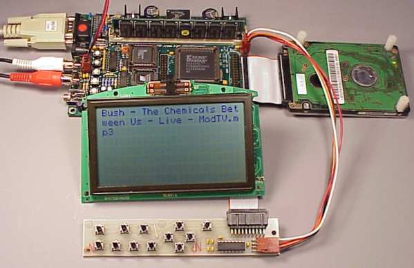 The display board actually has an 8051-based system on the back side, and the firmware that runs on the display board may be found in the 0.6.2.5 source code. When you build the code, the makefile will create "lcd.hex", which is the code that runs on the display board itself. "lcd.hex" is about 95% complete. Unfortunately, the JW-002 doesn't support flash upgrading, so you need to use an EPROM burner to program the display's firmware. The boards we'll sell (hopefully very soon) will have the firmware already installed, but to upgrade will mean a chip swap. "lcd.hex" only needs to have debounce and reporting code for those 12 pushbuttons added inside a timer interrupt routine. So far it's working pretty well, as you can see I just got the bugs worked out of the C to asm (drivers) interface, so the player's "main.c" able to do what the assembly code was able to do before. Using the display from the firmware is easy, now that the C-based firmware has the printf() function. It's just a matter of calling printf with the a couple display control bytes and the message to show. Inside 0.6.2.5's main.c, on line 202 is the printf that printed that filename on the display. At this point, the larger picture is still a bit more work to do on the drivers to fill in missing functions needed for really cool features (timers, file_uncache, buffered serial I/O), and just a bit more work on the display's code to allow those 12 pushbuttons to cause messages to be sent to the player. If you've been considering hacking on the project, but waiting for it to convert to C, now's the time to grab 0.6.2.5 and take a peek. You'll also need the very latest version of SDCC from CVS, as Johan fixed a bug just yesterday that allows SDCC to compile part of the code, and earlier in the week a critical (for using the display) bug in SDCC's string handling was also fixed. AS31 is also required, and the setup of all this stuff is easiest on a linux system (if anyone gets it to build under windows, please contact me with details). Not all of the system calls needed for really cool features are available yet (particularily file_uncache and timers), but they will be soon. The C code is now stable enough to try for some fairly complex features. The next thing I'm going to work on is getting the last bit of code onto the display board, so that the 12 pushbuttons will be able to send commands to the player. May 9, 2001: I fixed more bugs in the conversion to C, and now the firmware can actually play the first file! Of course, problems occur on the second one, but still it's pretty exciting to get the C version to start working. I should write a bit about the display. The basic news is that I'm embarrasingly behind schedule. As you can see from the photo of exactly one month ago, the hardware is more-or-less ready to go, but as always, there's more work to be done firmware-wise. There's actually two firmwares. There is the firmware that runs on the display board itself, which isn't easily upgradable. That firmware basically implments the communication protocol to receive commands from the mp3 player, like "move the cursor to this position" or "print this string". Except for getting the change of state on the pushbuttons into the protocol, the firmware for the display board is complete. What's so far behind schedule is getting the firmware for the mp3 player itself to send useful commands to the display board. Most of this code will ultimately be written in C, so it seemed like such a waste to write a bunch of that code in assembly and then discard it in the upcoming conversion to C. If you look compare 0.6.2 to 0.6.2.4, the first 870 lines of assembly in "player.asm" were removed and re-written as about 260 lines of C code in "main.c" and 50 lines in "startup.c". While it does delay the project, this conversion to C really is needed to be able to handle a more complex user interface. I'm pretty good with assembly, but not that good! Russ created a message board at Yahoo Groups, dedicated for this project. If you're interested in chatting with other users, give it a try. Please don't fill the message board up with questions like "when will xxxxx be ready?" May 6, 2001: I've spent almost all weekend playing with SDCC and converting the main program portion of the code from assembly to C. That's the easy part, really. The hard part is creating function prototypes for all the existing code that's going to remain in assembly, and making the "glue" code that allows the existing assembly code to be called from the C program. Some other ugly issues I've been putting off, like properly responding to interrupts with the banked code memory also had to be addressed. So far I've got fifty functions defined to tie the existing drivers and filesystem code to the C application, and most of them actually work. At this point, I've got the C application more or less written (functionally the same as 0.6.2.1), and it sort-of works after much debugging. Saddly, there's only so many hours in a day. In the spirit of ESR's "release early, release often", I put the code in its present state on the firmware page. I only posted the source, not a ready-to-use image file, because it really doesn't run just yet. Still, if you've been following this project and want to get your hands dirty (but not assembly-language dirty), take a peek at the C code. It's all in "main.c" right now, and it's only a few hundred lines of code to read (a lot easier than trying to make sense out of more than 9000 lines of assembly!!) May 3, 2001: This evening I finally put Tom's parameter storage code to use (after some edits to it). Version 0.6.2.1 stores the volume setting as a non-volatile parameter. It should be easy to add more settings to the non-volatile storage, like the file that was last played and the random number "seed", but at the moment only the volume setting is stored. May 2, 2001: I just put version 0.6.2 on the firmware page. Version 0.6.1.E has turned out to be quite stable, so I'm planning to call 0.6.2 "stable", unless I hear reports of significant problems in the next several days. The main change in 0.6.2 is proper support for using the board without a SIMM. Apr 22, 2001: Quite a lot has happened since my last update two weeks ago. We finally have more assembled boards in stock. They are "Rev B" boards, with a minor change in the power supply. The change makes the input range of the 2-pin connector 6 to 10 volts, instead of 4.5 to 6 volts. The advantage is that the power supply isn't easily damaged to applying too much voltage (say 12 volts to the 2-pin connector), and the TIP102 transistor doesn't run nearly as hot when the board is powered with 14-15 volts on the 12 volt input. For battery operation, six AA cells are needed with the Rev B board, instead of just four. I'm behind schedule with the display board beta test. I had wanted to send out beta test boards two weeks ago, but a week of travel and meetings put me a week behind with Veris (the day job, this MP3 player is in my off hours), so I didn't manage to do much with the MP3 player project in the last couple weeks. It's looking really good that it's actually happen this week. Also planned for the near future is a page with much more detailed info about the display board. It's always risky to make promises, but at the very least I will be working on this project this week and this page ought to get a couple updates through the week. A group of students at BYU did some work to try to add ATAPI device support to the firmware. They wrote these seven web pages about their project. The work is incomplete, but it looks like they did have some success implementing some of the low-level code. I know of one other person who's interested to try and implement support for ATAPI devices. Eventually this code could lead to support for CDROMs. For now, I'm going to stay focused on getting the display board working and on display and navigation features in the firmware. When the display stuff is mature, I'll probably look into this ATAPI/CDROM support, but I will of course accept patched in the meantime :) I also managed to get a USB Adaptor Board recently (from www.in-system.com, who has been acquired by Cypress Semiconductor and their old website has vanished) It's quite a bit smaller than the one shown in that photo. It's about 2.5 by 1.5 inches (6.4 by 3.8 cm), with the USB connector on the opposite side of the board. I haven't had time to do any testing with it, but it looks like it ought to be possible to get it to work with the player. The trick is to have it tell the player when the USB is active and have the player not attempt to talk with the drive. These boards are about $42 in single piece quantity, which is a bit more expensive than I'd like, but maybe that's ok? Apr 9, 2001: This weekend I made display adaptor board layout and etched three prototype boards. Here's a photo of one of the boards with a new display (still has the blue protective coving):
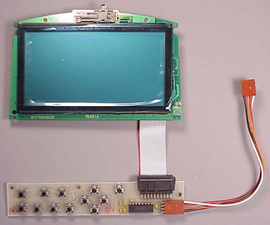 I actually wanted to be at this point on Saturday, as the firmware still needs a bit of work. I wanted to ship four beta test boards on Monday... it's really close, as you can see from the photo, but just a bit more work is needed in the code that goes in the chip on the back of the display board. The bad news is that it's not looking too good for getting much done on this project through the week. Tuesday is dinner I need to go to, and I'm flying out on Wednesday afternoon to visit a (Veris) customer on Thursday. It may next weekend when I can finally ship the beta test boards out. I made three tonight, and I'll probably make 3 more, and so far I've heard from 4 people who want to give these boards and the first firmware a try. Of course, we'll have some nicer "professional" boards made in a couple weeks, with the usual green solder mask, silk screen, and plate-through holes. It's looking like we're going to sell a kit with all the items shown in this photo, for $47. That's the display board itself, with a firmware chip installed that has the firmware needed, the 17 pin ribbon cable (attached to the board's connector), the adaptor circuit board with 12 pushbuttons, and the 4 pin cable to connect to the mp3 player. It's also possible to buy the display board from Earth Computer Technologies ($39), if you want to program an EPROM with the firmware and build your own adaptor board and cables. Soon I'll add a page with quite a bit more info about the display, including the firmware source code needed to make it work. Apr 3, 2001: Here's a little image I drew that shows approximately what I'm planning for the display adaptor board. The scale is 100 dpi, so the planned board size is 5.5 by 1 inch (14 by 2.5 cm).
 On the right side is a ribbon cable connector that will connect to the display board itself, and a 4 pin molex header that is a right-angle version of the one on the right side of the mp3 player. The design allows for 12 pushbuttons. The exact function of each pushbutton will be determined by the mp3 player's firmware, not the hard-to-upgrade firmware of the display board. Though not shown in the diagram, there ought to be space to put 12 pairs of holes so allow off-board pushbuttons to be easily connected. At this point, the big question is how to arrange the pushbuttons on the board? This drawing shows one possible scenario. I added the green text to illustrate some potential functions for the buttons, but keep in mind that the exact functionality of each button is due to firmware in the player, not the design of this board (which is what I'll be concentrating on this week). If you have any opinions or insights about how these buttons might be well arranged, now would be a really good time to email, but please please please, try not to get caught up in all sorts of complex details about menu systems, playlists, etc. All that sort of stuff is to come in the mp3 player firmware, but after this board is finished. Apr 2, 2001: This weekend Robin and I built up a few mp3 player boards from the extra parts we had. So the good news is that everyone who was waiting for a board (with a valid order) is getting a board shipped today. At the moment, we have just two boards left, and a small handful of invalid orders (shipping cost confirm req'd and not received, declined credit card, check/money order not received, etc). We also built up more of the 8051 boards, which means we're not in danger of running out of those and getting into this time-consuming business of trying to be fair about who gets the last few boards. (we should have plenty more mp3 player boards in about 2 ½ weeks). On LCD display board front, I've been having trouble actually getting a good number of them. On Friday I was told that a box of them is being shipped, so hopefully we'll have some to offer soon. We're planning to sell the display board a little kit, which will include the display circuit board with a ribbon cable attached, and a firmware chip installed to implement the command set. The kit will also include a little adaptor board that has 12 pushbuttons, a connector for the ribbon cable, and a 4 pin connector that's the same as the one on the right side of the board. Of course, we'll include a short 4 pin cable to connect between the boards. The adaptor board is simple, it's just one MAX232 chip and some capacitors and the pushbuttons. The MAX232 converts the serial signals, and provides a negative voltage which is needed for the LCD display. That little slide adjust on the top of the display allows the contrast to be changed, and the negative voltage from the MAX232 is enough for the right most setting to be really dark. I don't have all the costs added up just yet, but unless it means losing money, I really want to sell this display kit for under $50. It will also be possible to buy the display board itself, without the firmware installed and without the adaptor board and cables, directly from the vendor (qty=1). I'll post a page with more info about this, including the firmware source code and instructions to do-it-yourself, probably next weekend (if I actually receive the package this week). The display board I currently have, shown in the photo on March 7, has many mods on the back side for firmware development and other hacking, so it isn't a good example for testing and explaining what we'll actually be able to sell. My short term plan is to build up a few kits with "beta test" firmware, for a few adventerous souls who'd like to try the display right away (I have 4 people on my list so far, email if you're interested). Unfortunately, the display board isn't easily firmware upgradble. The firmware is in a PLCC socket and requires swapping the chip. It isn't downloadable like the mp3 player board. I have the firmware more-or-less finished (still a bit to do with the pushbuttons), but it's always possible that there's a bug or two, so I want anyone who buys one of these boards early-on to understand that they may need to pull the chip and reprogram it (we'll use flash on the first boards), or get a new chip if an eprom programmer with PLCC socket isn't readily available. In the long run, my plan is to keep the display board firmware simple and avoid adding features to it, and instead add fancy features into the easily upgraded mp3 player firmware. On the firmware front, I haven't heard any complaints about the out-of-memory bug with 0.6.1.E. I ran it for quite a while and I've been seeing some warnings from the memory allocation routines, which may not be a big deal as nothing bad seems to be happening. I'm starting to think that some of the problems I was seeing may have been due to damage to my board's power supply (that board with the yellow dot has seen a lot of abuse thoughout this project, which is why it has a yellow dot... so we don't ever accidentally mistake it for a new board that we would sell). There obviously is a need to do a bit of clean up in the code before a 0.6.2 release. As you can tell from reading this page, I haven't had much time to do much with the firmware in the last couple weeks. It looks like we've done just about everything we can do with getting more boards built and be fair and satisfy everyone who's been waiting, so hopefully I'll be able to get some real work done on the firmware and LCD board in the next week or two. The Rev B circuit board will have some minor changes in the power supply, which result in the lower voltage input connector having a range of 6 to 10 volts. A couple of people have been unhappy hearing about this change, so maybe it's worth taking a moment (in this already too-long update) to explain the change and the motivation behind it. It was my hope that the change would provide a 4.5 to 10 volt input range, but that didn't really work out. The new circuit will actually run a bit lower than 6 volts, but not near 5 volts. The biggest advantage of the change is that the low voltage input isn't easily damaged if you apply 12 volts. I had a couple people return boards with the 74AC14 chip blown, which was almost certainly due to applying a higher voltage to that input. The 74AC14 has an absolute maximum of 7 volts (though they will sometimes survive more... sometimes). In some cases, the 74AC14 will blow in a way that allows the supply to temporarily output too much voltage, which causes the FPGA or STA013 to also fail. The new mosfet driver chip can handle 14 volts. The 10 volt limit is due to the capacitors, though they can usually take a bit more voltage without trouble. Making the board more sturdy to abuse was a big concern for me. The other advantage of the higher voltage input range is that the linear step-down preregulator (TIP102 transistor) will have less voltage across it. When the board powers a laptop drive, this TIP102 part runs hot. It's still within its spec, but it can get very hot to the touch, particularily with a laptop drive that draws a bit more current. The original idea was that the hard drive would never spin for any long period of time thus limiting the temperature rise... but has you can see from the history of these updates, that has turned out to be easier said than done, with the 0.6.x firmware still not completely debugged enough to be called "stable" (though 0.6.1.E is pretty good). As far as motivation behind the design, the linear preregulator was done for two reasons... originally to allow a power supply I first designed for batteries to run from 12 volts, and to provide protection from the 60 volt spikes that will happen in a car if the car's battery is disconnected while the engine is running (I didn't want to have a fuse that blows). I originally wanted to run from four NiCd cells. It's looking like the 0.6.x firmware can run for 5-6 hours from four 1500 mAH NiMH batteries (available from Radio Shack), using the 0.6.x firmware and 16 meg simm... which is quite a bit better than Creative Lab's Nomad Jukebox! This new design will need six cells instead of four. I know that's a bit heavier and bulkier, but since the board is 5.75 by 4 inches (14.6 by 10 cm) due to using through hole components that hobbists can easily solder, the extra two batteries don't seem so bad, and the play time will be longer. The larger voltage range also means that alkaline batteries may have a chance, though NiCd or NiMH are much better at suppling the large current needed to start the laptop drive motor. For the distant future, one interesting idea I've heard is to actually build two separate 5 volt supplies, one for the drive and one for the board. This would be a major redesign, but the idea is interesting because then each supply could be designed and optimized for just its expected load range, instead of the current (difficult) design which needs to handle such a large range of load currents, and the supply dedicated to the drive could be completely shut off. I'm intrigued by this because it turns out that laptop drives draw a significant current even when in full sleep mode. My Hitachi DK23AA-12 drive measures 17 mA in full sleep. If anyone out there reading this is a switching power supply guru, I'd be interested to hear from you, particularily about how to get 5 volts at 1.2 amps from a 4 to 15 volt input (SEPIC, perhaps? ... currently using flyback). Well, for now I think the Rev B board will be a minor improvement, and if you really wanted to run with a 4.5 to 6 volt input, well, I'm sorry (though we have two assembled boards and a several kits left as of today). Mar 28, 2001: It's been a while since I updated this page. We ran out of the assembled mp3 player boards. I've been spending most of my project time working on getting the next batch of boards ready. I did end up making a minor change to the power supply, which turns the low voltage input range from 6 to 10 volts, instead of 4.5 to 6 volts. It's looking like we'll have the new bare boards next Tuesday, and then it's a two week process to get the boards assembled (it can be done faster, but the cost goes up sharply). This last week has been a not-so-fun job of counting all the parts and ordering the ones we're missing, which really isn't very interesting, but I thought I'd put an update on this page anyway. The processing of orders is usually pretty simple, but it gets complicated when we're almost out of stock. We also happened to run out of the 8051 development boards at about the same time, doubling the number of orders that need special attention, but those are fortunately back in stock again. Robin has been out of town most of this week, and I'm not nearly as good at it as she is (and I don't end up getting much done on the firmware). Well, with a bit of luck the last pending orders will be completed or canceled and we'll offer the boards to others who are waiting, and the board assembly will go smoothly over the next two weeks. Mar 19, 2001: I spent quite a bit of time playing around with tweaks to the power supply. Today the 2-pin connector on the right side of the board accepts 4.5 to 6 volts. I really wanted to widen the range to 4.5 to 10 volts (for Rev B boards), but it's looking like I managed to make it about 6 to 10 volts. I'm not so happy about not being able to run from 5 volts, which is such a common regulated power supply as well as 4 NiCd batteries. I'll probably do a bit more fiddling. Maybe 6 to 10 volts is ok? I received a bug report about as31, though it was the S-Record output format, so it doesn't effect this project which is based on Intel-Hex format. I did fix an annoying problem where the command line version wasn't returning error codes to the shell, which causes "make" to continue building when it should stop. If you're building the project from the source, be sure to grab this new version of the AS31 Assembler. Mar 18, 2001: I spent yesterday and this morning working on the display firmware. Most of the features described on the LCD protocol page are working now. I added more details to that page as I wrote the code for each part. This morning I got the scrolling to work. I also built a little prototype board with 12 pushbuttons. The display board firmware reads the buttons (3x4 matrix, 7 I/O lines), but a bit more work is needed for up/down detect, auto-repeat, and support in the protocol. I'm not sure exactly what functions will ultimately get programmed to the buttons, but the display board adaptor will be able to provide 12 buttons. I suppose 4 want to be for 2-dimentional cursor/selection movement and 1 for enter. The existing 6 buttons probably want to be duplicated, except random mode may turn into a menu choice. Right now the big question isn't exactly what to do with each button, but how to arrange them on the board that will fit just below the display. The 4 buttons for up/down/left/right probably want to be in a diamond shape. I'm imaging that this board will probably be about 1 inch high by 5 inches wide (2.5 by 10 cm), and a portion on the right side will be taken up by connectors and 1 chip. We're nearly out of boards. I've been putting off ordering more circuit boards, because I wanted to make some minor changes to the power supply on the next round of boards. The main change I've wanted to make is to replace the 74AC14 with a proper mosfet driver chip. I spent the afternoon tweaking a TPS2814 chip onto a board. That's the easy part... the hard part is that two of the inverters from the 74AC14 form a software shut-off circuit. The idea is that the firmware can turn off the power supply (the play button wakes the power supply up). I've never really done much to support this from the firmware. There's very little extra space left on the board and many attempts to build another shutdown circuit were not successful, so maybe I'll just leave the board as it was, with the 74AC14, or maybe I'll change to the TPS2814 and abandon the shutdown circuit. I did some playing with a LMC7211 comparator to make a shutdown circuit, and it's looking like it just might work. It's a SOT-23-5 surface mount package, and I've tried to avoid surface mount to keep the board easy to assemble from the kit. Everything's a trade-off, I guess, but these really are pretty minor tweaks to the power supply. Well, one way or another, I really need to order boards on Monday or Tuesday, so I'll have to make a choice and go with it for the next batch of boards. Mar 16, 2001: I'm going to try releasing beta test firmware very frequently, starting right now. I just put 0.6.1.E on the firmware download page. This version fixes the no-sound bug. There is still one major bug left, which I'm calling the out-of-memory bug. Eventually, something goes wrong in the memory manager and usually this results in a significant memory leak, which you'll see in those message about how much memory is available after each file is finished playing. In some rare cases, memory pages will get mis-managed in some way the triggers one of a few sanity checks that will abort the player and produce a very long dump of critical memory areas. If you're watching with a terminal and happen to capture one of these giant memory dumps, please email it to me. My hope is that releasing beta test firmware frequently will allow you to keep up with changes in the project and try out the very latest code, if that interests you. I could also use more feedback out how they're working, but please keep in mind that a bug report is much more valuable if you can reproduce it with the debug messages turned on and capture them to a text file attached to your email (type "DEBUG", or edit the code and uncomment "setb debug"). The only potential downside is that our little site has limited bandwidth and quite a number of people run those abusive archiver programs (Teleport Pro, WebZIP, etc). If this gets to be a bandwidth problem, I'll probably start removing older beta versions that aren't of much interest. Mar 15, 2001: It's looking like I may have finally solved the no-sound problem that happens with some boards. It turns out that the STA013 MP3 decoder chip requires a bit of time to initialize itself after a reset. The tricky part is that there is a code burried deep within the config file provided by the manufacturer (ST) that does a soft-reboot. They don't document this anywhere, and it's not mentioned in the suggested algorithm for sending the config data. I added a 0.6 ms delay into the downloading just after any writes to register address 16 (the soft reboot register), and this has completely fixed the no-sound problems on the board I have that reproduces this problem regularily. I emailed firmware images to the four people who've reported this problem recently, so hopefully I'll get some feedback about how this change effects their boards. If you have a board that sometimes boots up and produces no sound but says it's working, please contact me and I'll email you this firmware file. Feedback is really valuable with these hard-to-reproduce problems. Hopefully this no-sound issue will finally be fixed. Mar 14, 2001: Once more, I've fallen a bit behind on updating this page. I did quite a bit more work on the display firmware and fonts. I create this page with the LCD's fonts and another page with the planned communication protocol for the display. I still need to write quite a bit of the code for the protocol. That's probably happen this weekend. I'm hoping to have a good idea of pricing for these display boards by next week. I'm planning to have some small adaptor boards and cables to allow it to easily plug into the MP3 player and also provide remotely mounted pushbuttons. It'll take a couple weeks to get these boards and custom cables ready. If you're impatient and want to get a display as soon as the firmware is ready (and build your own cables and adaptor board), contact me by email. Recently I've been putting quite a bit of work into solving the no-sound bug that happens with a small number of the boards. Some times the MP3 decoder chip doesn't get properly initialized, or at least that seems to be what's happening. Most boards only very rarely have this problem, if at all, but a few boards do it much more regularily. Last night I finally managed to write some code that can reliably detect when the chip isn't properly initialized and it retries. Each retry takes about 2.5 seconds, and it seems to eventually get the chip initialized properly. I'm not happy with such a kludge, so I'm still working to try and find out exactly what causes the improper initialization, but at least this retrying allows boards to work properly. If you have a board that does this no-sound problem, please email me and I'll send you the latest beta-test code. Mar 7, 2001: I haven't posted here in a few days. Last Thursday I got a LCD display, which looks like a good choice for this project. It's 8 lines by 24 characters and includes an 8051 based system on the back side, so very little extra hardware will be needed to make it work. It's new (unused) from a surplus supply vendor, and it came without working firmware or any significant docs. They've got a very reasonable price on them, considering that it's got a complete 8051 system on the board and the display area is large, about 4 inches wide by 2 inches tall (5 by 10 cm). That's just the active area of the display, the board itself it only slightly smaller than the MP3 player board. Here's a photo:
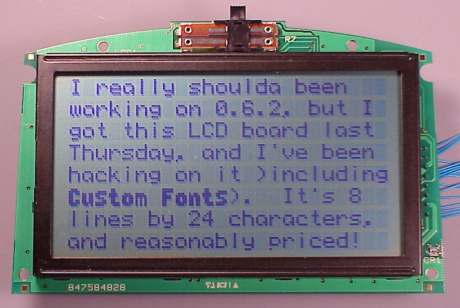
Feb 28, 2001: Fixed a bug where pressing the next or previous button while the file was still being read could cause file_close to be called before the IDE driver would finish processing all the queued read requests. There still seems to be another "no sound" bug, different than the one that I fixed on Feb 21. There's also some sort of memory management problem that shows up mysteriously after many tracks are played. Both of these aren't very easily reproduced (yet). I really want to get these last two known bugs fixed before a 0.6.2 release. Feb 25, 2001: Yet another bug fixed. This time it was a problem in the way cached FAT sectors were being indexed. It only tended to happen with certain fragmented filesystems. Tom actually sent the debug messages that exposed the problem. From there, it took an hour to write code to artificially recreate the bug, and then only a few minutes to actually fix the offending code. I'm still having some problems with the code... it may be that the fat32 code can't handle full concurrency with the IDE driver (which I enabled when I took out the workaround for the DMA bug). This problem is very hard to reproduce, so I'm currently running another lengthy test, and hopefully there'll be some useful info available tommorrow evening. Our ISP's router is still pretty shakey. They think that the problems are fixed, but they're not. I set up a little script to do pings every minute and log the result, and it looks like we're having a 5-15 minute outage about once every hour. That's pretty bad, and they'll be getting a call in the morning with my logged data. If our little web site hasn't been responding for you, well, if they don't get the act together soon we'll move to a different ISP. Feb 25, 2001: It looks like I finally figured out what was causing the occasional DMA errors (when not using the busy loop in 0.6.1). It was a small error in the FPGA config. Nothing an all-night debugging session (currently 4am) can't take care of.... Reading the drive is noticably faster with the busy loop gone. I really need to get some sleep. Later today I'll do quite a bit of testing. Feb 24, 2001: I've been working on the firmware this afternoon. I just fixed a bug which would sometimes cause only the first several seconds of a file to be played. On the no-sound front, three people who's boards reproduce the no-sound problem have tried the code. Two reported the problem fixed and one "got better". If your board does this no-sound behavior when it cold boots with 0.6.x firmware, and you read this before 0.6.2 is released, please send me an email and I'll send you the work-in-progress firmware to try on your board. It's becoming obvious that some problems are being caused by bad SIMMs. The SIMM detect code in 0.6.x only tries to detect the SIMM size, and it will properly detect even very bad SIMMs. Version 0.5.x will work with many very faulty SIMMs, because it only uses a tiny portion and only stores the data for a very short time. Now that 0.6.x is making a lot of use of the SIMM, it is sensitive to faluty SIMMs. Still, it's amazing how long it can take for a bad SIMM to finally cause a crash, as it appears that bad SIMMs usually are partially working. I only have a couple bad SIMMs, so if you happen to have any 72 pin SIMMs that are bad, I would really like to get them for testing. I really need to learn a bit more about testing DRAM and write a good memory tester into the firmware, so in the event of a bad SIMM, at least it could abort and run version 0.1.1 (which doesn't use the SIMM at all). I also did some more shopping for a nice display. I want to have a relatively large graphical display, but I don't want it to end up costing a fortune. Feb 21, 2001: Last night I reorganized how the STA013 MP3 decoder chip is initialized, which is might solve the bug where the player will sometimes start up and appear to be working normally (via the serial port), but no sounds is made. I sent a copy off to Patrick, who's board/system seems to be able to reproduce the problem (the 3 boards sitting on my desk almost never do it). We've been having problems with our upstream ISP. They've been down for over 5 hours today! They claim they are replacing some hardware that is supposedly the cause of the recent outages. If their uptime doesn't improve soon, we'll probably switch to a new ISP. The company was sold several months ago, and the guy who ran all the technical aspects left 4 months ago, and since then their reliability has gone downhill. If you've been checking this page and the server hasn't responded, well, I'm sorry about that, but there's not much we can do when our upstream provider to the internet is off-line. Our linux-based server's uptime is 219 days today. I wish our ISP was that reliable. Feb 18, 2001: Today I fixed several bugs in the code, including a really bad one in the memory manager initialization (which often resulted in the player reporting out of memory right as it started up). There's a bug where sometimes the player will start up with the audio muted, and a cold reboot usually fixes it. I took out the muting at startup, and so far I haven't seen this problem again. It's hard to tell if this is really fixed or I just got really luckly (powered the board off/on about 50 times) 0.6.1 also had several types of crashes involving the pushbuttons, mostly due to changing the program's state at the time of a button press, rather than waiting until a state where the change makes more sense. I added code to continue reading while paused (if the drive was spinning) which means the cache gets filled while paused and the drive shuts off as soon as possible. I also changed the drive wake-up to not do a hard reset if the drive wasn't in sleep mode, which makes rapidly pressing the next or previous buttons much more responsive. I added another call to free_fat_memory to avoid temporarily leaking some memory when the next/prev buttons are used. I also fixed a few places where interrupts weren't being disabled when they needed to be. I updated the plan above, shooting for bug fixes only for 0.6.2, hopefully to finally have a stable firmware that does caching. Feb 15, 2001: Bad news, 0.6.1 isn't looking nearly as stable as I had thought. Three people have reported lock-ups so far, so it looks like I'll have more work to do on it this weekend. I did a test run with 4 NiMH AA size batteries, and it played 112 files before the batteries dies! Unfortunately, the 0.6.1 doesn't handle a dead battery gracefully, as the board reboots when the drive is started. I need to add a check for lots of reboots in a row and do a proper shutdown. It's going on the to-do list for 0.6.2. Feb 14, 2001: I just posted 0.6.1 to the firmware page. Tom sent a patch that fixes the pushbuttons, and I just took care of the memory leak from the FAT sectors. We both ran various incremental revs of this code for a couple days and it looks pretty good. There are a few known problems, which are mentioned on the firmware page. Please download and give 0.6.1 a try, and let me know if you see any problems. If no major problems turn up by the end of the weekend, I'll send a message to the announcment mail list. There's still a lot to do, but 0.6.1 is really a major milestone. Feb 13, 2001: Last night and very early this morning I did some more work on the firmware. The audio glitch problem is some sort of a strange problem where DMA transfers are targeting the wrong place in memory, but it happens very infrequently, never happens (so far) if I add some code to just wait for the DMA to finish. The read performance hit isn't really bad, so I'll probably leave this in for 0.6.1, in the interest of getting a nice DRAM caching firmware rev posted that is actually usable. Tom's long filename code is really nice. It's pretty cool seeing "10,000_manics_these_are_the_days.mp3", after having looked at "10_000~1.MP3" for so long! Tom also sent a patch today that adds much of the pushbutton support back in. I promptly broke some of it, doing an overhaul of how the low-level code handles the pushbuttons. The idea is to separate the detection of user actions (timing sensitive) from the main program which services them (without deterministic timing). The new code passes these events in a fifo, instead of fiddling with flags. The idea is to be able to convert the main application, which runs in a loop without any particular timing, to the SDCC C compiler. The low level functions, many of which are timing critical, will remain in assembly. Of course, all this other new code (caching FAT32, queued request IDE and playback, etc) are designed for a clean separation between the main application and the low level drivers. I want to get the application part converted to C as soon as reasonably possible. Well, I could go on about the details, but the short story is that the code is really coming together and 0.6.1 is getting close, with caching, pushbutton support, and no significant delays reading data. I just reorganized the "What's Planned Next" section at the top of this page, to reflect what's currently planned for each upcoming firmware rev. Feb 11, 2001: Today I spent the entire day, about 14 hours, working on the firmware, trying to get to 0.6.1. I wrote a new main loop which can begin playing a file while it's still being read from the drive. Getting things running concurrently exposed dozens of bugs that don't show up in 0.6.0. I wanted to get all the drivers converted to interrupts, but so far only the MP3 DMA to the decoder chip is interrupt driven. I've been battling little "glitches" in the audio output all night, due to various bugs and missing checks here and there. There's still some small problems, but it's getting much better. The really exciting news is that the overall performance is really much better. Reading from the drive is just under 1 Mbyte/sec, and that's with the IDE driver still running without interrupts! Now that the MP3 transfer is interrupt driven and the play request queue is working, many seconds of data can be queued up. Tom Parker sent two patches, which I still have to work with and include into 0.6.1. His first patch provides non-volatile parameter storage, which will be really nice for things like keeping the volume setting, starting up on the same track, and probably a lot more things when the display is available. Tom's other patch adds long filename support. Very cool. I really want to play with these, but I can't stay awake much longer (2:30 AM, been coding since 10 AM). Feb 4, 2001: I started the new User Photo Gallery page today. Later today I'll start the technical documentation table of contents page, and then update the links at the top of all these MP3 player pages (not fun work) to point to those two new ones, so that all the new pages are easily reachable without having to read this recent news page. Feb 3, 2001: Yesterday and today I did some of the work to convert the IDE driver to being interrupt driven. The "file_cache_work" function now uses the transfer pending status bit on each block, to avoid using a cached FAT sector group that hasn't been fully transfered yet. In 0.6.0 the IDE driver is run immediately after file_cache_work until is gets to the idle state, which makes things simpler and easy to test, but for good IDE performance the transfers really need to be able to happen concurrently with file_cache_work, as it can take quite a bit of CPU effort to prepare a cluster transfer, but once the cluster transfer is in the request queue, the IDE driver will (hopefully soon) be able to work on transfering that data while the FAT32 code does the work to prep more transfers. I could go on about other optimizations already in the code that are intended to work together with this, but that's old news... I also added a little optimization to remember the last FAT sector group, so in the common case of low fragmentation the next cluster can be found much more quickly by avoiding the search for the correct FAT sector in the cache. This should make more CPU time available to the main program, in the long run. I added a bit of code to correcly mark which files depend on each FAT sector group, so that it'll be possible (not written yet) to free the unneeded FAT sectors in file_close. I wrote the free_fat_memory functions, though it's still untested. 0.6.0 leaks memory because it never frees FAT sectors, even after all the files that needed them are closed. I wrote a first attempt at the interrupt service routines... but they're not complete enough yet to try them. I drew a schematic for the power supply. There's getting to be several of these technical documentation pages, and I'm planning many more. I really ought to edit the links at the top of all these pages and add a link to a table of contents page for the technical documention. Aside from this new schematic page, there's the STA013, library functions, and memory map. I'm also going to start a User Photo Gallery page soon (to be linked near the top of all the pages, probably between the FAQ and this Recent News page), where I'll post photos that I receive. If you'd like to share a photo of how you used the board, please email it to me and I'll post it. Jan 31, 2001: Ok, it ran for a few hours, so what the hell. Version 0.6.0 is now available on the firmware download page. At the last moment, I added a bit of code to turn the verbose debug messages on/off by using the Vol+ and Vol- buttons. Even with the messages off, the read speed is approx 100 kbytes/sec. There's no attempt to begin reading the next file while the last one is still playing, so you'll wait about 40 seconds of silence if the next file is 4 megs. (much longer with debug messages turned on) This firmware release is mainly to get some code out to others who've been wanting to hack/contribute, and to give you a look at the new caching. If you load this firmware, it's a bit difficult to get rid of it. Typing "QUIT" crashes (there is a mix of the new/old IDE drivers causing this if the drive is in shutdown, and the user interface isn't called properly while reading/caching). To get back back to the monitor, you'll need to cold boot, and press 'S' (as descibed on the upgrade page). There is only a 1/2 second wait for the 'S', though you can press it earlier in the boot process. Please, there are many bugs left in this code, so if you do report a problem, make sure you've been capturing the verbose debug messages. If you want firmware that works nicely, this is not the rev for you... stay with 0.5.1 until more of the bugs are worked out, the main program uses the caching in a better way, and the IDE driver gets up to good performance. If you've been waiting to get your hands on the new FAT32 code to do some coding, now you can. Please let me know what you have in mind, so I can plan for it. Jan 30, 2001: Tonight I fixed even more bugs and got a very simple main program going. It reads the file (very slowly due to the lots of verbose debug messages), shuts off the drive and plays it from the cache, then starts up the drive to read the next file. No pushbutton checking or other features... but it seems to be working pretty well (if the SIMM fills up, it only plays the part of the file it was able to read). It doesn't try to read from the drive while also playing. All those nice things will come, but this is the very first working player based on the new FAT32 code with caching. I'm going to let it run for several hours, and if it doesn't crash, I'll release this as 0.6.0, which is really only useful as a developer release, but I need to get some code in the hand of other folks who've been wanting to hack on the code. It's not even midnight yet... (I've been up til about 3 am nearly every night for the last week working on this code.) I'm going to go rent a movie and have a couple beers! Jan 28, 2001: Today I wrote the dir_read function, which uses file_read to grab the raw directory bytes. After fixing bugs in file_read, and debugging dir_read, I kept getting strange failures, but at random places in the directory. Well, after much investigation, it turns out that there was a timing bug in the dram controller. The timing problem occurs very infrequently and until I wrote the directory parser, there just wasn't a large enough number of accesses to the dram to really expose it. In fact, I finally had to replace all the movx instructions with a call to a little function that reads the memory 32 times and compares all 32 reads to see if they were the same. The problem would only show up 3-5 times out of many thousands of calls to this function! Well, after a few hours of FPGA hacking (not that long, considering that the Xilinx software is so slow and takes 15 minutes to recompile the FPGA, using a 800 MHz PC), I lengthened the time allowed for precharge after a refresh cycle, and that fixed the problem. I really wanted to release a firmware rev tonight, but I really need to get some sleep. More or less all of the needed FAT32 functions are written and seem to be working (need to update the library page), and I have two little test programs, one that reads the first file into the cache (100 kbytes/sec) and then plays it with the drive off, and one that prints a list of all the files in the main directory. Tommorrow, I'll throw together a little main program that does the same features as 0.5.1 with the new FAT32 functions. Jan 26, 2001: I just got about 1 second of playback from cached data!! Tonight I've fixed dozens of bugs and it's really exciting to hear a bit of sound, even if it is only 1 second and doesn't work every time. Still more bugs to fix, and the dir_read function has to get written, but hopefully I'll be able to salvage some code from 0.5.1 for that. It's really starting to come together now! Update (3:10am), I fixed more bugs in malloc_blocks, file_cache_work and file_read_block and it's now playing an entire 6.1 meg song from the cache! Polled/sync IDE driver read performance sucks (only about 100 kbytes/sec), need to work on that and write "dir_read" this weekend. Time to get some sleep... Jan 25, 2001: Another late night coding session... wrote all the code which will read data after it's already in the cache (much easier than getting from the drive into the cache), and the new playback code, which now has a queue of blocks of MP3 data waiting to be played. I spent a couple hours updating the library functions page. It now has a status indication for each function, so you can see roughly how far along they are, and I finally got around to documenting the file access functions. This documentation stuff is time consuming and less fun that writing the code, but it'll let you know where things are at, and (hopefully this weekend) when an initial release of the code is out, if you want to hack on the program you'll at least have some documenation about what these functions are supposed to do. The initial release will be built with a polling loop, that will run the IDE and play drivers by polling. These are meant to be interrupt driven, which will give much better performance to the IDE driver. I want to release something as soon as possible (working), even if the data transfer performance isn't optimal. The new code is designed to be converted from this polling to using interrupts, so with a bit of luck it'll only take a short rev or two to get the performance up to where it should be. A very important aspect to this project, which is mentioned in a couple places on the library functions page, is the caching strategy. The initial release will have only a very simple caching strategy. The file_cache function gives the application code complete control over what portions of what files and directories will be cached, and when the drive will be active vs in sleep mode. If you're interested in getting involved in the code, perhaps when the application level part is converted to C, put some thought into the caching strategy... what files to cache, how much of each, when to decide to uncache data, and when to hit the panic button (spin the drive up just in time before running out!) Jan 22, 2001: I spent the whole day today working on the code that puts the cached clusters into a linked list and does lots of other little things that will allow the cached clusters to be used in useful ways. There are a lot of complicated cases to deal with. I split the caching operation into two functions, a "setup" function that doesn't actually do any loading, just takes care of lots of computation and stores info into the file descriptor table, and a "work" function that the main program calls repetitively until the file is completely cached. This scheme is much more efficient... it avoids seeking though FAT sectors unless absolutely necessary. Nearly all the code needed to get a file loaded into the cache is written, and tommorrow will be a major debugging session. Today I exchanged emails with Tom Parker (who sent a patch for 0.5.1 to display long filenames), and I've wrote a fairly detailed description of how the main program will use these lower level functions. I added this text to the library functions page. If you're interesting in hacking on the code, please read this description in the "File/Directory Reading" section to get an idea of where the project is going and what low-level functions will (hopefully soon) be available for building cool features (playlists, ID3 tags, long filenames, etc). All this low-level restructuring doesn't actually do those cool features, but it'll make coding them possible. It will remove the defragment requirement, and it will give DRAM buffering, though the effectiveness of the buffering depends on how good the main program's scheme is for choosing what to request be loaded into the cache. Also, several people have been asking about the LCD display recently... I have the 128x64 lumex display connected and some code that's able to write pixels at selected locations. I'm planning to work on the display once this major rewrite of the FAT32 and IDE code is working. I'm also thinking about making the board support cheaper text-only displays (the really cheap ones unfortunately are surplus and are not consistantly available, which sucks for putting a lot of design work into a board and the code). The lumex display itself if $45, and I'm hoping to make the adaptor boards for $25-30. I know this isn't cheap, but so far it's about the best I've been able to find for a pretty cool display that's not a while-supplies-last surplus item. In any case, without these more reasonable ways to deal with files and directories (and subdirectories), it just isn't too realistic to do much with a display, so this FAT32/IDE code needs to come first. Jan 21, 2001: I've been working more or less round-the-clock this weekend, finally getting the FAT32 and IDE code re-written for caching with the DRAM. So much as happened to the code in the last couple weeks, and particularily in the last 48 hours, but it's getting late so I'll avoid a really long message like the one from a couple weeks ago. Here is a text capture of the latest firmware, which is loaded up with dozens of messages that tell quite a bit about what the code is doing. I hope this give you a bit of an idea of where it's at. I'll add some comments in green to explain a bit about what it's doing. I've a lot of momentum on the project right now, so I think I'm going to try to take a day or two off work and push to get a working firmware rev going. If I do manage to get a day or two off work, I'll update this page tommorrow.
    MP3 Player, Version 0.5.??, Jan 21, 2001             <-- not a real firmware rev, lotsa stuff still broken!
    Copyright (C) 2000, PJRC.COM, LLC

    Type 'QUIT' to return to the monitor

    Configuring Xilinx XCS10XL FPGA Chip: Ok
    Reseting IDE Devices
    Initialize Memory Manager                            <-- this actually initializes FAT32 and IDE drivers also :)
    Found 16 meg SIMM
    malloc 8 blocks: 0021 0022 0023 0024 0025 0026 0027 0028
    Configuring STA013 MP3 Decoder Chip: .........Ok
    Waiting for Hard Drive to be ready
    .
    Found IDE Master
    Set multiple mode, status=50                         <-- the new IDE driver uses multiple mode...

    Reading Master Boot Record
    Found FAT32 Partition at LBA = 0000003F              <-- these are (more or less) the same startup messages
    Reading FAT32 Volume ID
    Volume ID looks ok
    Sectors used for FAT tables: 00004C70
    Reserved Sectors: 0020
    First Data Sector at LBA = 00004CCF
    Cluster size is 32 sectors (each sector is 512 bytes),
    Clusters will be cached in 4 block groups (each block is 4096 bytes)
    Root directory starts at cluster 00000002
    Testing new FAT32 code:
    fopen, fd=0                                          <-- program opens root directory
    file_cache, fd=0, bytes 00005E03 to 00007E02         <-- program asks for a portion to be cached
      Req'd cluster offset 000001 to 000001              <-- the second cluster on this file is needed
      next_cluster, current=00000002
        search for FAT sector 00000000                   <-- FAT sector index 0 is needed to find this cluster
        FAT sector not found in list                     <-- this FAT sector isn't in the cache (yet)
        currently cached blocks w/ FAT sectors: 0000
        new block to insert into array at index=0000
        moving fat sector lookup array
    malloc 1 blocks: 0029                                <-- the memory to cache this FAT sector is malloc'd
    doing ide state: waiting for not busy
    doing ide state: idle
    ide: reading 4k at lba=0000005F into block 0029      <-- the IDE driver reads the FAT sector into the cache
    doing ide state: waiting for DRQ
    doing ide state: waiting for DMA complete
    doing ide state: waiting for not busy
    file_cache, fd=0, bytes 00005E03 to 00007E02         <-- program asks for data to be cached (again)
      Req'd cluster offset 000001 to 000001
      next_cluster, current=00000002
        search for FAT sector 00000000
          bin_search: begin=0000, end=0000, middle=0000
        FAT sector found in list at index=0000, blk=0029 <-- this time, the FAT sector is found in the cache
      read cluster 000073EC (offset 000001)
    malloc 4 blocks: 002A 002B 002C 002D                 <-- 16k (four 4k blocks) are allocated to hold the cluster
    doing ide state: idle
    ide: reading 4k at lba=00004CCF into block 002A      <-- IDE driver reads first part of the cluster
    doing ide state: waiting for DRQ
    doing ide state: waiting for DMA complete
    doing ide state: waiting for not busy
    doing ide state: idle
    ide: reading 4k at lba=00004CD7 into block 002B      <-- IDE driver reads second part of the cluster
    doing ide state: waiting for DRQ
    doing ide state: waiting for DMA complete
    doing ide state: waiting for not busy
    doing ide state: idle
    ide: reading 4k at lba=00004CDF into block 002C      <-- IDE driver reads third part of the cluster
    doing ide state: waiting for DRQ
    doing ide state: waiting for DMA complete
    doing ide state: waiting for not busy
    doing ide state: idle
    ide: reading 4k at lba=00004CE7 into block 002D      <-- IDE driver reads last part of the cluster
    doing ide state: waiting for DRQ
    doing ide state: waiting for DMA complete
    doing ide state: waiting for not busy
    doing ide state: idle
    doing ide state: idle                                What happens next, you may wonder...
...A lot more work is still needed, for example recognizing that the requested range is fully cached, correctly linking the clusters to a list so the reads from the file will work properly, handling cases where a latter part of the file is cached before the beginning, properly marking FAT sector per-file usage bitmaps (so that a call to fclose can deallocate the FAT sectors for that file if they aren't needed by other open files), a lot more testing (for example, the binary search has minimal testing because I haven't built any substantial lists of cached FAT sectors yet), and a new main program that actually uses this neat new stuff to achieve playback. Still, it's pretty exciting to finally start getting some data cached, and using FAT sectors from the cache instead of looking them up on-the-fly. Jan 3, 2001: Last night I did a bit more work on the code, mostly getting the just malloc'd FAT sector buffer added to the list of cached FAT sectors, and all the misc housekeeping details (I hope). Tonight I'll start on actually servicing the read requests. Will update this page later tonight it there's any really exciting news. This recent news page was getting pretty long, and using up quite a bit of our limited server bandwidth, so I chopped all the news before Nov 20th and put it on the history page. Jan 1, 2001: I spent most of the 3-day weekend writing, or at least trying to write the DRAM buffering support code. Robin and I also put together more MP3 player kits. I added a contribution to the STA013 page from Ed Schlunder (that'd been sitting in my inbox for a week) and they wrote the last major missing section. The code in 0.5.1 and below works by reading one sector at a time. The code waits for the sector to be read and then give it to the STA013 chip for playing. That's very simple, and it's designed for when the FPGA didn't really support the DRAM and the only memory available was the 256 bytes in the 87C52 and a sector-sized fifo in the FPGA. In the absence of a firmware release, I'll write a bit about how it's intended to work, so you can see a bit of what's going on. There is a "file_open" routine which is similar to a C library "fopen"... you give it the first cluster number of the file (which you get from the directory info together with the filename), and it returns a file descriptor byte. The current code allows 16 files to be opened. I might increase this to 32 files. "file_open" really only just initializes some info in memory that gets used by the other functions. All the real work is done by a function called "file_cache", which I've been working on all weekend. You call file_cache with the file descriptor from file_open, a 32 bit beginning byte position, and a 32 bit length. This file_cache function has the job of getting that portion of the file cached into the DRAM. It never waits for data to be read! It always returns as quickly as possible. To get data cached, the program will need to call file_cache repeatedly until it returns a status bit that indicates the data is actually cached. The first thing file_cache does is compute which clusters offset within the file are needed to satisfy the requested byte range. Then, it tries to follow the FAT cluster-chain to find the actual clusters on the disk those are. To do this, it does a binary search on an array of pointers to all the cached FAT sectors, to find the one holding each part of the list of clusters that leads to the one needed. If any of these looks fails to turn up the required FAT sector, then it is read. How sectors are read is interesting. The file_cache routine calls "malloc_blocks" to get a block of memory that will hold the sectors. It sets a "read_pending" bit on a small data structure that describes the block, and then adjusts the array of pointers to the cached sectors, effectively adding this one to the list. It then writes a "read_request" into memory and returns to the main program with a status bit that indicates the file isn't cached yet. For now, I'm having the main program run some code which polls this list "read_request" messages and either commands the drive to featch the sectors, or begins a transfer of the sectors (using DMA) to the memory (which was already malloc'd by whatever wrote the read_request message), or sees that the DMA is done and clears the "read_pending" bit, removes the "read_request" and sets up for the next request to the drive. Right now this is a simple routine that the main program calls, but later when this stuff is working, this will turn into an interrupt routine. Many other speed-ups will happen evenually (and appear as TODO comments in the code), but the right now this is a major restructuring of the way everything runs and the idea it to just get it going in a non-optimal way. The "file_cache" routine keeps getting called (by the main program), and when the FAT sectors are in memory, it'll locate the required cluster numbers, and create similar read_requests for them. (they get stored in a link-list from the struct indexed by the file descriptor, not together with the FAT sectors) When it has requested the last read for the last cluster, it'll return a status code that the file is cached (or at least will be very soon, and no more file_cache requests are needed). I'm planning two "file_read" functions... one that copies a small part into a buffer allocated by the main program, and another the returns a pointer to the next 4k block of cached data. (the more difficult read-into-buffer is partially written) Both of these will only read data that's already cached. The only function that causes disk activity is "file_cache". The "read" that copies will be useful for building a nice routine that parses directories better (including long filenames), and it'll be useful for reading ID3 tags, playlists and other user interface required data. The block-based read returns a pointer to a cached block without copying anything, and is intended mostly for playback, together with a "play_reqest" list, similar to the "read_request" list for the disk drive. If this all sounds complicated, that's because it is! It's been a long uphill battle to get this far. It's a lot harder to build a nice general purpose memory-managing interface like this than it is to just read sectors one-at-a-time. There is still much coding to do, but the good news is that how it's all going to work together is really becoming much clearer, and a substantial portion of file_cache (and the lower level malloc, bin_search, and other functions) are written and seem to be working. I could go on about the details, but maybe I'll just say a little bit more about how I'm planning to use these functions once they're working. I haven't updated the library functions page yet... Imagine the (hopefully very near) future when these functions are working.... the main program will open the main directory, call to have it cached, then parse for the first file. It'll open that file, call to have it cached, then read the first several dozen blocks and generate "play_request"s for them. Then it'll open the next file files, and request them to be cached. It'll probably monitor what portion of the memory is still free as it does this, and perhaps when available memory gets under some threshold, start opening a lot more files, but only requesting the first portion and perhaps the last portion (ID3 tag) to be cached. When these requests nearly consume all the memory, it'll generate a special "read_request" that tells the IDE driver to spin down the drive and put it into full sleep mode. All the while, the main program will be monitoring if there is space to enter more "play_request"s and keep reading more blocks of the current file to generate them. As the blocks are used, a "file_uncache" function gets called to free the memory, and when a file is completely finished, "file_close" completely frees all the memory used by that file and returns its file descriptor back to the list of available to be opened again. Some sort of estimate of how much more playtime is cached needs to be made as the blocks are played, and when it gets low, more files are opened and the "cache_file" is called, causing the drive to spin up and read more data. Because cache_file can cache small portions, a number of files into the directory (or playlist :) can be cached with just enough in memory to start them playing and have enough time to spin-up the drive to get the rest. It'll also be possible to have the part of the file with the ID3 tag cached, but not the rest of the file. The idea is to build a good library of functions to manipulate files and more or less automatically handle all the memory allocations, so that the main user-level application can be built to do all sorts of really nice things. Well, that's all a lot of vapor, but it really is becoming much clearer how these functions are going to work "behind the scene", and a good part of the code is running. A lot of the difficult groundwork, like defining the structures in memory that'll keep track of all this stuff are in place. I'll try to keep this page updated with news and as soon as some of this stuff is working in a somewhat useable way, I'll get a firmware rev made. Dec 28, 2000: I didn't get any coding done over the X-mas weekend, but we did (finally) get some more bare circuit boards. We also got more of the 8051 dev boards, just as we ran out of those boards :) We spent some time assembling more boards. Last night Robin printed more labels for the kits. I think we have all the other parts, so with an afternoon of sorting and counting parts, we should finally have the kits available again! Dec 20, 2000: This evening I answered emails, lots of them. I'm going to give up on a group of really old ones, from early August to the first week of November. (I did answer lots during that period, but not all) If you sent me a message back then and I didn't answer, I'm sorry. I'm (finally) caught up now, and I think I'm getting better about keeping up with the higher volume of email since the slashdot article. It feels good to finally have an empty inbox!!!! I'm going to try and keep it that way. Dec 19, 2000: Yesterday Peter Kovacs added a couple more links at his mp3projects.com site, particularily to the new Using the STA013 page. I started this page a couple weeks ago, since I've been getting quite a bit of email (mostly from students) asking how to use the STA013. Now that it's going to be getting a good number of hits, I figured I ought to at least get some good info onto it. Last night I built that little breadboard and added the photos, and I spent a quite a bit of effort to make a few low-bitrate test clips, that fit into 32k of memory and actually have several seconds of a recognizable line of a well-known song. Tonight I added the four little schematic images. Dec 17, 2000: I've been working on the firmware this weekend, and the firmware page now has version 0.5.1. I finally added the code for the volume and random play buttons. I really should have done it a long time ago (sorry to keep you waiting so long). I also added a patch from Dave Johnson that fixes the bug with the play/pause button (thanks Dave). I changed ide_init to automatically detect if the drive is an IDE master or slave. If the memory manager doesn't find a SIMM, the it will attempt to run version 0.1.1, which is also included. Version 0.5.1 still doesn't do any significant buffering and it still needs the drive to be defragmented. I'm making some progress there... most of the memory management library functions are included inside this firmware, though they're mostly untested. Dec 14, 2000: I'm sorry I haven't updated this page in the last two weeks. I've been a bit busy and saddly I haven't been putting as much time into this project as I want to. To make up for that, here's a bit of kind-of good news... I just posted a DRAM test firmware release to the firmware page. Don't get too excited, this firmware works almost exactly like 0.1.1 (no significant buffering), but it does use the DRAM (a very tiny portion), with DMA from the drive to DRAM and DMA from the DRAM to the MP3 decoder chip. If you have a bit of time, I'd really like to hear how it works with your SIMM and hard drive. Also, does the SIMM auto-detect find the correct size of your SIMM? If you have a laptop drive that frequently "skips", does it perform better or worse with this new version? (my Hitachi DK23AA-12 is mysteriously working better) Is the audio quality the same, worse or better? Does it seem to use more power than 0.1.1? Everything is supposed to look the same as 0.1.1 (including the play-play-pause bug), so if you notice any differences please let me know. I rev'd the firmware to version 0.5.0. The idea behind this is that I'll probably back-port a few features to the 0.1.x firmware, for anyone that doesn't want to use a SIMM. Also, getting the hardware config more or less finished is a big step, so 0.5.0 seemed cool. There's still much work to be done in firmware to actually take advantage of all these new capabilities. Writing all the code to manage memory and files is turning out to be a big project, and I'm still trying to get a grip on how to put it all together (of course, being busy and not spending a lot of solid time coding doesn't help much). At this point, there's a lot of really low-level work, but if you want to help, now you can grab 0.5.0 and be up-to-date with the memory map. At least for some time, I'm not planning on any more significant hardware config changes, so it's relatively safe to write code using the memory map. As usual, I'm behind on emails. If you've got a board and need help, put "URGENT:" in the subject. If you've got a patch to the firmware (not just thinking about it), put "PATCH:" in your subject line. These help me get to the more urgent emails first. Nov 27, 2000: Well, it looks like I'm a slacker. I really wanted to get a new firmware rev out-the-door yesterday, but instead I ended up taking most of the weekend off to spend time with Robin and have some fun. Well, I did do a bit... it's more or less firmware work from here. I started a library function documentation page to keep track of the code. Making all these nice library functions is a lot of work. I keep telling myself to just do a quick and dirty hack to the original code. Nov 21, 2000: I put some work into starting a little library that will manage the memory. It's looking like quite a bit of work, so I may just put that aside and do something simple like filling the SIMM with raw data using only a head/tail pointer, so that I can get a working DRAM enabled firmware rev done by the end of the weekend. Ultimately there needs to be a memory manager that works together with the a library to do caching of the files, directories, and FAT sectors, but that can all come later on. As it comes together, I'll probably write a page about how it works and how to use it. I had another little project going, organizing our engineering team's effort in the Veris company canned food drive. Those first four palletts are from our group (approx 4000 pounds). The good news is that a lot of needy folks will get some good food to eat, and this little side project is finished and won't distract from a firmware rev this weekend. Nov 19, 2000: Get ready for some awesome news! The first test of the DMA to the MP3 decoder worked!! It was just a simple test with 60k of data read into the DRAM and a single DMA operation to send it all to the decoder. Still, it was really damn exciting to hear sound come out! More programming is needed to make the actual player app use the DRAM and DMA. The sound "sounded" fine, but it'd probably be a good idea to do some looking at the waveforms, just to make sure everything is as it's supposed to be. It's getting late, so I'm not going to do a lot more with it tonight. Tommorrow evening is planned for another bit of work on the canned food drive (I'll post a picture on Tuesday), so it'll probably be Tuesday or Wednesday when I next put a lot of work into the code. There are still some bugs to work out, (the ALE glitch problem showed up again a couple times today), and my test board still has the power on/off circuit ripped apart. Also today I did quite a bit more testing with the DRAM and wrote a program that identifies what size SIMM is installed. I updated the memory map with details about how each SIMM size is mapped, and of course I changed the status of lots of the registers :) Now I really don't like to make promises about release dates (everything always takes longer that you thought it would).... but I think it's safe to say that next weekend (Nov 25/26) will be the first firmware that uses the DRAM. It may not have a lot of cool features (like only using the first 4M), and there may be some bugs, but that's the goal: to get a working DRAM firmware rev next weekend. It's been a long day, and I need to take a break. Nov 19, 2000: Yesterday I put in most of the remaining support for the MP3 decoder DMA transfers. I had quite a bit of trouble with a little counter circuit, which counts how many of the bits from a 16 bit DMA transfer still need to be shifted to the MP3 decoder chip. The xilinx fast carry logic is hard to use, and this morning I figured out that I had a couple RLOC parameters wrong. I spent quite a bit of time this afternoon chasing after this strange problem where the board reboots during some DMA transfers. I kept chasing after the soft power off circuit, which turned out not to be the problem at all. I finally clipped the transistor and other parts off the board, and the problem remained! That was really strange, until I realized what was really going on. There's a signal attaced to the 3 pin power connector, which is intended to detect when power is applied from a PC, and the IDE controller is supposed to tri-state all its pins, so the PC can use the drive. Well, a long time ago I was having some trouble with the DRAM WE pin, so I also connected the signal to that pin, which is connected via a diode to the power supply on/off circuit, so that the board will be forced on while in use by a PC. Writes to the DRAM were actually going through that diode. Without DMA, you can't get enough writes in a short enough time to cause a shut off, but the DMA can do it. With this fixed, the DMA is a lot more solid. My board is still pretty hacked up from lots of fiddling today... I'll have to repair all the cut traces and put another transistor back on to make sure things are really working, but at least this big mystery is cleared up. The next step is to write some code to load up the RAM with some MP3 data, and try to DMA transfer it to the MP3 decoder chip. Nov 16, 2000: Ok, once more I'm a bit behind in updating this page (and swamped in emails, as always). I did put in a few long sessions since the last update, but I haven't had much time to work on the project in the last few days. I'm going to put some serious time into this weekend. Here's the developments (now a few days old) since the last update on Nov 8th. This turned out to be quite long and very technical, so if you just want to know what's coming next, skip to the last paragraph. The initial excitement about getting a DMA transfer was followed shortly by discovering several bugs. The easy one was that it was always transfering two bytes less than requested... easy to fix. All the other bugs were not easily reproducable, and I didn't even see some until doing many many tests. My first instinct, which turns out to be only part of the story, was that it must be a timing problem. Well, I've never really done much with the timing constrains and static timing analysis tool. In fact, I even had to make a tech support call to the local Xilinx FAE (I try never to need tech support). After several hours learning how the software worked and coming up with a viable strategy to properly specify timing constrains (which were realistic and the software could meet when compiling the FPGA), I learned of two problems. The static timing tool kept crashing or giving really bad results, which I eventually learned was because it saw a combinatorial loop. Technically, there was a path that could have been a loop, but the control signals for some of the muxes were mutually exclusive. Of course, static timing analysis isn't a true simulation, so it can't know that. After a couple attempts at rearranging the busses in the FPGA design (and of course re-doing stuff accordingly), I finally got rid of the combinatorial loops it was seeing, and then I began to see where the timing was really not good enough. I probably should have known, as it turned out the timing problem was in the address mapping circuitry. That circuit takes address info from the 8051 bus, from a tiny ram (inside the fpga) that holds all the page translation settings, and from the DMA setup registers. Given a few signals from the control state machine, it has the job of turning all that info into the DRAM and IDE address lines. There are a number of cases, so it's not exactly a simple thing... too complicated to explain in this already long winded message. Anyways, I had made several changes to this circuity over the last couple months, usually by adding on extra parts. It also had some left-over circuitry from the original DRAM controller design, that the optimizer wasn't detecting and trimming off. The xilinx software is supposed to optimize combinatorial logic, but it only works for simple cases, and this was not. It turns out the software was implementing all this stuff in the fpga with over 20 levels of logic, ouch! It's amazing it even worked at all. Well, I spent an all-night session and redesigned the address mapper with a lean-and-mean approach (I've learned quite a bit about what it does and doesn't need to do since the first try). The new one only takes a few levels of logic and it's much faster than needed (about 11-13 ns, the design allow 34 ns, minus a flip-flop setup time). Functionally, the new address mapper is almost the same, but it no longer uses any config bits, so the DRAM_SIZE_CFG register on the memory map page is now obsolete. The new address mapper works automatically with whatever SIMM is installed (4, 8, 16 or 32 megs). In the case of 16 megs, the memory appears as four blocks of 4 megs. This happens because of some details about the way SIMMs are organized. I'll have to add some specs to the memory map page about exactly how each simm size is mapped. In the long run, these details will be burried in the memory manager library and will be almost invisible to the main application code. Well, as I made massive improvements in the timing all over the fpga design, a little ugly problem that's plauged the design for a long time got much worse. It's a bit scary when a problem occurs as things get faster. This little problem involves an occasional error reading from just about anything. It's strange, sometimes data dependent (tends to happen when a previous bus cycle transfered all ones, or something like 0xFE). Usually it has gone away when I recompiled the fpga with a minor change, and sometimes shown back up again. Well, with all the timing much faster, it was here to stay, as I made changes (recompiling now takes 15 minutes with all the timing constraints), I can work on it. This little problem still isn't 100% resolved, but I did get several solid hours of work on it and I'm pretty sure the cause is glitches on the ALE signal from the 87C52 chip. I can't see them on a 60 MHz analog scope, but based on making changes in the way the circuits grag the address bits, I'm pretty sure that the 8051 is sometimes putting tiny glitches to ground on the ALE signal when it's supposed to be holding it high. For now I was able to make the problem go away with a simple hack... but it really needs to be solved by sampling ALE and not using it to drive edge sensitive flip flop clock inputs. If you want to see this little ALE glitch problem in action, put a SIMM in your player (firmware 0.11), run while connected with your favorite terminal emulator (I use seyon in linux), and type "QUIT". Then press "T" to run a little DRAM test utility. This uses the very first DRAM controller. The code writes four 16 bit words and then tries to read them back. If you look at the asm code, you'll see what a pain this is (with the new DRAM controller, you set up 4k page translations, and then just use the DRAM like normal memory). If you have a good SIMM installed, it will usually pass the test, but sometimes it will fail. If you read the code carefully and scrutinize the results (I have had one person email who actually did), you'll see that the original DRAM controller auto-inc's its 32 bit address registers after a read or write. In the failed cases, not only does it not read back correctly, but the inc fails as well. I now know it's because the controller "heard" the wrong address and didn't actually execute the operation as requested. This little DRAM test, though flakey, is there so that when I test the boards I can make sure all the wires on the board are properly connected to the DRAM, and it's one of the FPGA compiles that happened to have a bit better timing on the ALE signal and therefore suffers from this little problem. After feeling really good about finally getting the timing greatly improved (and certain to meet all the requirements), and getting some progress on the ALE glitches, I started writing some code to do benchmarking on the DMA. With the overhead of setting up single sector transfers and using a polled busy loop (instead of interrupts) to detect the end of a transfer, the sustained transfer rate looks like about 1 Mbyte/sec. It may be possible (not hard) to get a 2X improvement with a more optimal driver. Not fast by Pentium-class computer standards, but certainly fast enough to fill the SIMM. That's reading the same sector over and over, so it remains to be seen if the disk drive will hold things up. As I worked with benchmarking the DMA speed, I hit another very strange problem. Sometimes a DMA transfer would cause the board to reboot or shut off. I tried different input voltages and batteries instead of a power supply, and it made small differences, but the problem persisted. I got worried that perhaps my little switching power supply wasn't able to keep up, though current measurements said the board was running well below the maximum (the board runs near the max only briefly as the drive pulls a lot of current to start up its motor). I tried dozens of different test transfers (if only xilinx could compile a FPGA as fast as AS31 compiles 8051 code). I tried doing a 3 Mbyte transfer, and I found that I could do this over and over for hundreds of runs and never hit the bug, but short DMA bursts would trigger it sometimes. Very strange. I really only spent less than an hour chasing after this bug, so I don't know much about it yet... it was at the end of a very long session where I finally figgured out the ALE glitch issue. I'm a little worried that it might be a noise sensitivity issue with the "soft" shut off circuit in the power supply. It's still much too early to tell. More tests are needed! So, dear reader (you managed to read through all that!), that's more or less what's happened lately. Tonight I'm going to do some work on a canned food drive and tommorrow Robin returns from a business trip, so it'll probably be Saturday when I really dig in again and get some progress on these bugs. For now, the ALE glitch issue is hacked, but I'll probably put the fast timing back and redo the address capture in a way that's totally insensitive to these glitches. The DMA burst length problem needs many more tests to get some real info about what conditions cause it. So far I don't have a test case that always makes it happen, so that'll be the first goal. I know a lot of people are itching for a firmware rev with the large DRAM buffer... I want to make it happen soon. After these bugs are resolved (and I add the STA013 DMA channel, which should be easy), I'll probably do some quick hacks to the existing code to add buffering and make a firmware rev, so everyone can get buffering asap. In the interest of getting something going as quickly as possible, it'll probably just use a 4 meg buffer regardless of what simm is installed... at least for the quick hack. After that needs to come some code to manage memory, files, etc, and a conversion to C, so that it'll be possible to implement complex features like playlists and a cool display. All that code infrastructure work will take some time, so the initial goal will be to hack buffering into the existing (simple) code and get a firmware rev soon. Nov 8, 2000: Very cool news: Woke up in the middle of the night (technically Nov 8th) and changed the IDE test program to use DMA, and it looks like it's working! I actually spent more time reading various parts of the ATA specs and it took a bit of fiddling to get the code that uses the DMA right, but I was finally able to read sectors and the drive ID info using DMA. I upgraded the status of most the registers to "looking good".... I really need to spend some more effort to check their exact values and make sure everything is correct, but after several minor mistakes in the asm code, the DMA hardware worked on the first try! Very cool. It's looking like actual DMA speed for the player will be somewhere between 1.2 to 2.5 Mbyte/sec, which is not quite as fast as I'd like, but it ought to be ok to fill the SIMM in several seconds. Of course, now my sleep schedule is really messed up. I better get some coffee and get into work. Tonight I'll probably nap and then stay up all night doing real testing. Now that the IDE DMA is running, the MP3 decoder DMA should be pretty simple, since it re-uses most of the same hardware and their timings. Nov 6, 2000: Updated the memory map with the rest of the new regsiters and descriptions of how they work. Nov 5, 2000: Worked today on the DMA... I added the inc/dec circuit that increments the addresses and decrements the counters as it does a transfer. After puting some thought into how the code will work, I decided to switch from 32 bit address registers to 16 bit registers that use the same memory paging as everything else. This means the memory that is receiving from the hard drive or supplying the MP3 decoder must be mapped, but it will make writing the code simpler. It'll also make it easier to later on add things like a DMA based memcpy(). After I got the inc/dec circuit in and re-arranged things, I broke the DRAM support, but fortunately it didn't take long to find the error. I really wanted to make a firmware rev today... but all the major things are in place, so with a bit of luck the remaining parts will be small enough to get reasonable progress in the evenings during the week. Oct 28, 2000: Very exciting news: the new DRAM controller now has working PIO access to the IDE interface. It can correctly communicate with the drive and read sectors. Still haven't tried to write a sector yet, but it ought to be able to write. This is only the PIO access... DMA is close behind. The DMA is really needed to make the DRAM buffer useful, since PIO access from a slow 8051 won't be able to fill the DRAM quickly enough to make it worthwhile. Still, this is a major step, and it proves that the vast majority of the hardware is correct. DMA shouldn't take long now. Today I also created a memory map / register list for the new design. I tried to explain what these things do a bit, so if you really want to know what's up with the project, take a peek at that page. This page is ultimately intended to document the hardware for anyone interested/crazy enough to hack the really low-level code. Right now, please keep in mind that the register locations and functions are changing. I wanted to get caught up on all those old emails today... most are older than 2 weeks and I'd guess everyone there just figures I ignored them. I will eventually get to them all.... but today's been a really exciting day, the first time to actually have working DRAM and IDE access at the same time! Oct 26, 2000: I spent all night answering emails... and still a long way to go. I think I've got under 200 to go! When I finally get the inbox empty, I really need to stay on top of the emails. I've purchased four LCD displays that are under consideration for the project. I did a bit of work with them tonight. As a practical matter, the firmare won't be able to many interesting things with the display until there is more memory available (DRAM controller). These are the four displays I've got:
Oct 25, 2000: Last night I worked on adding the IDE port access to the new DRAM controller. I put all the states into the control state machine, but it'll take an evening of writing some code to see if it's working. I just added some nice hyperterminal screenshot that were contributed to the upgrade instructions page. I'm working backwards though my inbox... I want to get all 300 messages that've piled up answered before the weekend! Maybe that's a bit ambitious, but I can't keep putting it off forever. Oct 23, 2000: Very exciting news! The new dram controller is finally talking with the dram. The new design is very different from the original one, and allows the firmware to directly use the dram, instead of accessing it through a bunch of I/O registers. I spent Sunday and this evening working on it, and it's finally coming together. There is still much work to do... the FPGA config with the dram controller still can't communicate with the IDE drive or the MP3 decoder chip. The new design has a one-hot state machine design, which turns out to be a lot easier to add onto and modify (though it uses more resources in the fpga), so with a bit of luck I might be able to get an intial release in another week or two. I really wanted to get all this done by now, but at last the light at the end of the tunnel is in sight! I'm still hopelessly behind in emails, some are almost three weeks old now. Oct 16, 2000: I haven't updated this page in a while. Last weekend (Oct 7th & 8th) I worked all Saturday and Sunday on the DRAM controller. This weekend we got more boards ready, and so we have them in stock again. We're out of bare boards, so to make more kits we'll have to get more boards made (mid/late November). I've been a bit occupied with some changes at work, so I've not spent as much time on this project during the weekdays. Working on the DRAM controller last weekend, I made some major changes. It's more or less taking a step backwards before taking two steps forward. The original DRAM controller uses registers to control everything, so it's not easy to access the DRAM. For playback only, that's not such a big deal, but for writing general purpose code in C, the DRAM really needs to appear as general purpose memory in the address space of the processor. The new controller does this (well, it's not working yet). It maps the DRAM as a large group of 4k pages, where 30 registers configure which fifteen 4k pages appear in the address space of the CPU at any particular moment (the top 4k is reserved for control registers and future expansion). Because the 8051 doesn't have wait states, the new controller executes one operation per 8051 bus cycle, and then waits for the next 8051 bus cycle to begin. Data cycles access registers, the IDE interface, or the DRAM (depending on the address), and during program fetches from the flash rom, the controller executes DRAM refresh, DMA transfers, or NOPs. When it's (finally) working, I'll write a couple web pages with a detailed description of the memory map and a complete register list. I'm planning to write some libraries to handle all this low level stuff, so it'll be easier to write code for the project without having to worry about these things. Built on top of those will be libraries to accessing files and directories, which manage using all the available DRAM memory for caching data. I'm about two weeks behind in emails... hopefully I got all the urgent ones. Someday soon I need to just spend a serious all-night session and answer them all. Several people have sent improvements for the web pages or firmware patches. When I go through all the emails (hopefully in the next few days), I'll try to get all these posted. Sep 30, 2000: Once more, I'm really behind in emails. If your message is urgent (you've got the player and need some help), please put the word URGENT (all caps) at the beginning of your subject line. I'm going to spend a couple more hours today on emails, and then try to spend the rest of the day on the firmware and dram controller. Also, Todd Elliot contributed a cool IR Remote Control Decoder, which I just added to the site. Sep 26, 2000: Actually, it's 1 AM, more or less still Monday night. I finally got a bit of time to work on the firmware! There's a new firmware rev with minor improvements available now. This evening the Crystalfontz display showed up. I haven't connected it yet. It's late and I need to get some sleep, so it'll have to wait a bit longer. Also, I'm getting behind in emails again (still under 50). If you have an urgent message, please include the word "urgent" in all caps in your subject line. I want to be more responsive, but letting emails sit a while gives me some time to work on the firmware! Sep 24, 2000: I finally got caught up with all the emails. I've answered over 600 emails in the last several days... if I missed yours, please send it again (but please please check the FAQ page before asking a question). I really need to add a page with troubleshooting tips. I just added a section of the FAQ page about this. It really deserves its own page with much more detail. I also just added some more of the common questions to the FAQ. I also added a number of new questions to the FAQ, and broke it into two pages. Sep 20, 2000: It looks like we've run out of boards. We are making more and they should be ready early next week. We also have some boards set aside for pending orders, which will become available if any of those orders are canceled. We'll fill the orders we get in the order they're received. I added another item to the urgent firmware changes list. Sometimes Microsoft uses partition type 0B for FAT32, and other times (all my tests) they use 0C. This might be related to the bios settings for "normal/large/lba". They don't document this in their FAT32 spec. Currently the firmware looks for type 0C. I'm planning to get all these urgent firmware revs, and maybe some of the no-so-urgent ones done this weekend. Also, I'm terribly behind on my emails. I've got a couple hundred emails piled up, and we've not managed to send out the emails with tracking numbers for all the packages we shipped in the last few days. If you sent me an email, please be patient. I'll try to answer soon. Sep 19, 2000: It took all day and all night, but all the orders we've received are either shipped (last group from tonight will go to UPS in the morning) or had a problem and we couldn't fill the order for some reason (shipping charge authorization required, credit card charge declined, invalid info, etc). Emails for those orders we couldn't process will go out tommorrow... I need to get some sleep. Sep 18, 2000: It's late, technically the morning of the 19th. We managed to ship a little less than half of the orders from Friday and the weekend (slashdot effect). I got a bit nervous about sending out so many boards without ever having used the DRAM controller on them, so I spent the morning and early afternoon developing a simple DRAM test. I also added a check with the 'scope on the NPN transistor on the drive's IRQ line, because the code doesn't make use of this interrupt, but it may in the future. The new test takes more time, and I had to re-test all the boards we'd already finished. It's a good thing, because one board (that had been assumed ok because it played) had a solder bridge on this transistor. I was only able get about half of the needed boards ready in time to get them out to UPS. As we processed the Visa/Master cards, there was a snag right at the end. I called the bank, but the people who can fix it are on east coast time. It sure was painful heading out to UPS, looking at the last few boxes, ready to go, but we couldn't process any more cards! Tonight I got most of the rest of the boards tested and packaged, so I won't have to do a lot tommorrow to fill the orders. Robin's going to call the bank early, so we can get the credit card processing going again. We always process cards as we package the boxes for shipping. We actually ran out of packing material, but I was able to run out and get some more. It's been a really long and frustrating day. I just sent out emails to everyone who's packages didn't go out today. If you're in that group, I'm really sorry. It's looking really good for getting the rest shipped Tuesday, Sept 19. It's also looking pretty good for shipping the orders that came in on Monday. Sep 17, 2000: I've finally answered all the emails received over the last few days. A few of my replies bounced, so if you sent a message and didn't get a reply, you're probably in that group. Sep 16, 2000: Well, the slashdot effect was more intense than I could have imagined! All the images were hosted at our upstream provider, so for every 5k html file they were sending about 100k of images. The web site is back to normal, but my mailbox is still slashdotted. I'm working though all the messages, but it may be several days until they're all answered. I just added a FAQ page, based on the emails I've answered so far. We received quite a few orders for boards. Fortunately, we had enough boards nearly finished that it's looking like we'll be able to ship all the orders received Friday on Monday morning. Robin and I are busily working away to put the final few parts on all those boards and get them properly tested. Robin's going to send emails to everyone we're sure will get their board shipped on Monday. I really want to get back to working on the firmware, so I can get those first few urgent items taken care of, and hopefully get the DRAM support going soon. I've had a lot of requests for ATAPI/CDROM support, so maybe that'll have to get raised up to a higher priority. Sep 13, 2000: Added a page with pinouts and power supply connection info. I spent quite a bit of time getting the firmware ready for a GPL release... added a Makefile, README file, GPL notices to the source files, cleanup out lots of old unused bits of code accumulated throughout testing the board, etc. The complicated part is that the data files for configuring the board are merged into the final executable code, but they're not GPL'd, so a exception is supposed to be added for them, or at least that's what the GNU guys suggested when I asked. I took a stab at it. I'll finish that part up soon and hopefully get the code on-line tonight. Robin's returning from being out of town, so if she gets and early flight and isn't really tired, we might spend some time together instead. Sep 12, 2000: I'm still working the add information about the new player to the web site. Tonight (technically early morning) I created this errata list, which is based on a list Robin wrote up after we built the first several boards. This nearly completes the assembly diagram pages. Here's my to-do list for the website:
Sep 6, 2000: The website has been unavailable since about midnight, due to some sort of equipment failure with the phone company. If you're reading this, they probably fixed it. Sep 6, 2000: The boards and kits are finally available! It's been a lot of work getting everything ready. The boards are working quite well. Two small mods are required. We're including an errata sheet with the kits, and I'll put it on a webpage together with lots of other info in the next couple days. Like the original prototype, the board sounds great. I spent quite a bit of time on the 4th and 5th working on the firmware. I fixed many little bugs with the FAT32 code, and the code now provides quite a lot of info about what's it's doing as messages on the serial port. The non-upgradable firmware in the 87C52, which is a modified version of PM2, now has the ability to let you abort auto-starting the player, and I added a number of little bits of code to help manage the 128k of flash as two banks of 64k. The firmware is working with standard FAT32 filesystems created from windows. The code requires the drive to be defragmented, because there is very little buffering without the DRAM. The firmware has all the code to follow a fragmented cluster chain, but without buffering there is not time to be reading the FAT sectors while playing a file. This defrag requirement will go away when the DRAM is supported, hopefully sometime soon. Before working on the DRAM, I'm going to put a bit more work into the DRAM-less firmware. Currently only two of the pushbuttons do something. The other four will be supported very soon. The firmware also only searches the main directory for MP3 files. I'm going to make it search 2 or 3 levels of sub-directories. From the emails I've been receiving, it's very clear that I need to create new up-to-date web pages ASAP. I'm sorry it's so confusing. I'm going to start redesigning the MP3 player portion of the site tommorrow. Aug 31, 2000: We received the first few circuit boards yesterday evening, and I've built the first board and I'll be testing it this afternoon. Here's a photo of the board:
The next step is to add the board, kits, and parts to our on-line store so that we can begin taking orders for them. We currently have about 20 boards and the rest are expected today or tommorrow. Robin and I are planning on working to build boards all weekend so that we can ship them on Tuesday. I should also mention that the firmware currently does not make use of the DRAM, so there is very little buffering, and the drive can not spin down (high capacity NiMH batteries last only about 1 hour with the drive spinning continuously). It will take me some time to merge the DRAM controller with the other FGPA player hardware, but the good news is that when this is ready, anyone who has the board will be able to flash upgrade to get DRAM support. The other issue with not having DRAM is that the hard drive must be defragmented before it is put into the player. There is also a larger copy of the board photo, where some of the chips are more readable. Aug 28, 2000: Robin and I have been spending quite a bit of time preping components and getting ready to make a bunch of boards. I've made dozens of orders for parts from various distributors, and our living room is filled with boxes and parts. We spent part of Sunday moving the phones and printer around, which required getting under the house to pull more wires (not fun). The new arrangement makes it much easier for Robin to process an order. Most of this doesn't involve the computer, so I've not updated this page in a while, and I'm horribly behind in answering emails. If you have an email message sent to me, please be patient. I'll try to get to them soon. The guy from the circuit board place called a couple days ago. The boards will be delayed a bit, because his wife who was pregnant and expecting in a couple weeks had a blood pressure problem. They delivered early, and she and the baby are fine, but ended up taking a few days off. We're expecting the boards a bit late, but with some luck we'll be able to get some built and shipped over the weekend. Soon I'll be adding the list of items to our on-line store, and then I'll be sending emails out to everyone on the notify list. Aug 21, 2000: Tonight I spent all evening counting parts and making a list of all the missing parts I need to buy. There's a lot of resistors, capacitors, etc. Just one missing part, even a resistor, will turn into not being able to complete boards or kits! Aug 21, 2000: I sent the board files out today to get a bunch of boards made. I added a few parts to prevent overcharging the battery. I also snuck in a resistor to keep the drive in hardware reset until the xilinx FPGA is configured, so it won't spin up early and waste power. I also added a connector and another diode which should allow the computer to power the board and let the FPGA detect that the computer is connected and tri-state all the IDE pins. This is intended to allow the entire player to be inserted into a PC, like a removable drive, so it'd be easy to copy the files on the drive. This feature is untested, but I think I'll be able to get it to work. Now it's just waiting for the boards to get made. Actually, I have quite a bit of work to do on the firmware, which includes adding the DRAM controller (already designed as a separately), and ordering enough parts. I'm always a bit nervous sending out board files.... what if there's a mistake? Well, the prototype showed the few places where I mis-connected wires, so hopefully I fixed everything and didn't add any new errors. It's not the end of the world to have to add a mod wire or two, but it sure is nice when the board is perfect! I've got my fingers crossed. Aug 19, 2000: Just when I thought things were finished, one more ugly problem has turned up.... I connected the the 12 volt supply (reduced to 6 volts by a transistor) and the battery both to the switcher input, so if both are connected at the same time, far too much current is dumped into the battery, which overcharges it rapidly. There really needs to be something to prevent the battery from overcharging. I've got a few ideas for this... all involve adding more parts which really don't fit on the board. I'll probably mount the input transistor vertically to buy a bit more room and put a larger heatsink on it. The reset problem turned out to involve the crystal oscialltor not starting up in some cases where the switching power supply was not able to start up gracefully because the input power sagged a few volts under the start up load. Fortunately, this has been fixed, by improving the supply a bit and mostly by adding a 220k resistor in parallel with the crystal. Aug 16, 2000: Got it playing from the hard drive, but without any buffering in the DRAM. The xilinx chip sends the data very fast... the board can easily handle 320 kbps MP3 files (maximum MP3 bitrate), with the 8051 running at only 7.3729 MHz! I just played a few 320 kbps files! I still need to combine the DRAM controller stuff with the IDE interface.... I'll probably do this next week after the boards are ordered. The xilinx chip is very unforgiving of any errors, and it's really hard to tell what's wrong when it doesn't work. Most of the evening it was sort-of working, and it all turned out to be needing to sync the DATA_REQ signal from the STA013 before feeding it into the next-state logic that controlls automatically feeding the MP3 bitstream into the decoder chip. I'm still having a couple minor hardware problems, which need to be fixed before the board is sent out. The main hold-up right now is that the 8051's reset circuit doesn't always properly reset the chip, which really must be fixed. I really want to get the boards made as soon as possible, but needs to work. The good news is that the analog signal sounds great.... but tommorrow I'll give it a try with some much nicer speakers. So far, it looks like there aren't any noticable problems with noise on the analog signals. Aug 14, 2000: I got sound to come out of the STA013 for the first time. This chip is much harder to use than the Micronas part which only requires resistors on some of its pins! It's finally working together with a CS4334 DAC chip, and all the hard work just ends up being a bunch of code and about 4k of data stored in the flash rom chip. Aug 13, 2000: Been working on testing all the hardware this weekend. Things are looking good, but it's going slowly. Firmware download and xilinx chip are good. STA013 is talking via I2C, but I have yet to get any audio.... just hooked up the DAC and all the analog parts tonight. Here's a photo of the board which now has almost all the parts on it.
Aug 11, 2000: Made a lot of progress with the board today. The microcontroller wasn't running because it's EA pin was floating... because of another part not yet soldered to the board and no plate-though holes on my prototype. The flash chip is working and I can download to it. Next step is to get the bitstream into the FPGA from the microcontroller instead of Xilinx's JTAG downloader. Things are looking really good. I should take another photo now that most of the parts are soldered to the board... I'll certainly do this Sunday evening if not sometime sooner. Aug 9, 2000: Been working on the switching power supply. It was originally not able to deliver the power required to spin up the drive. It turns out the problem was in the thickness of the traces where the over-current sensing resistor is located, which are already quite wide, but not wide enough. I will probably need to have the boards made with 2 oz copper, or a "build up" plating process. These are the sorts of things this prototype board is made for discovering, so that there (hopefully) won't be such problems with the actual boards to be made soon. Aug 6, 2000: Today I etched the first trial of the new circuit board. It's not fully assembled, and it hasn't been tested yet, but here's a couple photos so you can see what the new player will look like:
This board is 5.75 by 4.0 inches, the exact size of a standard hard drive. There are 12 mounting holes, four in the corners of the board, four on the top and bottom sides that mate with the bottom of a standard hard drive, and four around the center region of the board, which allow a laptop side hard drive to be mounted. There are no tall parts in the area where the laptop drive mounts, which should allow a laptop drive to mount about 3/8 inch (9.5 mm) above the surface of the board. The board has both standard (2.54 mm) and laptop (2 mm) type connectors, located vertically aligned with the location of the similar connector on each type of hard drive, to make it easy to connect a very short IDE ribbon cable. The board features a switching power supply along the top and a 72-pin SIMM socket for a large buffer memory. The switching power supply is designed to run a laptop drive (5 watts max). For a standard drive, an external 12 volt power supply will be needed. The 44 pin PLCC socket will hold a 87LV52 microcontroller, and the large 84 pin socket holds the Xilinx FPGA chip, that will provide a DRAM controller and IDE interface, with direct IDE to DRAM block copy, and automatic DMA data transfer from the DRAM to the MP3 decoder chip. The firmware and FPGA configuration are stored in a 32 pin Flash ROM chip, which will be located just below the microcontroller. The firmware and the Xilinx hardware are fully flash upgradable. Not yet soldered to the board are 6 pushbuttons, which are next to the audio outputs. These buttons will provide Play/Pause, Next, Previous, Random Shuffle, and Volume +/-. The small 4 pin connector (also not soldered yet) on the far right is intended to provide connunication with a LCD display and additional pushbuttons.
This photo shows a better look at the user I/O connectors. The 9 pin serial port is intended for firmware upgrades. A (very slow) download will be possible, though the primary way to get files onto the drive is to put the drive in a PC and copy them onto it. Two audio outputs are available, standard line-level on the RCA type connectors, and an amplified headphone output. The power jack next to the 9 pin serial port is intended for 12 volts, unregulated. It is possible to run the board from the 12 volt system in a car via this connector. The circuitry has been designed to handle the very nasty conditions that can occur in a car's electrical system. The small 2-pin red connector (on the far right in the top photo) is intended for connecting 4 NiCd or NiMH batteries. Here is a photo showing how a laptop drive can be mounted to the board. The drive fits over a section of the board where there are no tall parts, which allows the entire player's height to be only as tall as the SIMM and/or 20 mm tall capacitors in the power supply. A short ribbon cable is needed to connect the drive to the board without taking much room.
Aug 3, 2000: I've taken this entire week off from work so I can concentrate on getting the new player finished. I've been working on the circuit board layout for the last few days. It's nearly finished, but then those last several nets always take the longest, since the rest of the board is so full of wires. I've also been ordering components, so I'll have parts in stock for people who want to build the player, or want one fully assembled and tested. It's hard to know how many people are really going to want the parts... I'm shooting for enough for one hundred complete boards. That's nothing compared to Diamond Multimedia, but since I'm doing this whole thing out of my own pocket, it's about as much as I can afford. The MP3 chip, FPGA, microcontroller and transformer are expensive, and all the little things add up, so it seems like a lot to me. Still, I'm a little worried about running out, since some of the parts aren't easy to re-order. This project has been vapor long enough, and the last thing I want is to have a kick-ass player and no more parts available for people who want to make it. The circuit board is 4 by 5.75 inches, the exact size of a standard hard drive. It has 12 mounting holes, four in the corners, four that mate with the bottom of a standard hard drive, and four that mate with a laptop drive. It has both the standard IDE connector and the smaller 2 mm spacing laptop connector, each positioned on the board at the same height as the mating connector on the hard drive, so it'll be easy to connect the ribbon cable. The area on the board where the laptop drive should mount has only low profile (3/8 inch, 9.5 mm) components. I am switching to the STA013 chip instead of the MAS3507D. It's a little less hobbist friendly, but it costs less. $32 is a lot to pay for a single chip! Unfortunately, the STA013 is still expensive, but it'll save everyone about $10, and that saves me $1000 since I'm buying 100 of them! The board has 2 RCA connectors for line-level output, a 3.5 mm stereo headphone output, a 9 pin D-Sub connector for firmware upgrade, and two power connectors... one for a battery and another for an unregulated DC power source (including a car's 12V). There are 6 pushbuttons. The firmware will use these for Forward, Back, Play/Pause, Random Shuffle Mode. The other two are intended for volume control. The board has a small connector intended for a remote LCD display. I hope to make the display board in September or October. There is also a bus expansion connector to enable designing a high-speed download (USB, bluetooth, etc). For now, the primary way to get data in and out of the board is to put the hard drive into your PC and just copy the files onto it. The board is fully flash upgradable. The FPGA data is stored in the flash rom, so even the logic circuits on the board are flash upgradable. My initial firmware doesn't have a lot of features, but as cool things are added, everyone will be able to download them into their boards. The firmware will be free (LGPL'd), so anyone is free to try and add cool features. I will probably provide the device drivers, FPGA config, board layout and schematic under a "non-commercial personal use only" license, to make it legally difficult for a big company to steal the design and mass produce it. With a bit of luck, I'll be etching my first test board in a day or two. I'll post a photo when it's built. There'll almost certainly be some things to fix, but the plan is to get the ball rolling on having a bunch of professional boards made, so that everyone who's been waiting will hopefully not have to wait past the middle of the month. If you've been waiting for a board, it won't be much longer now. Jul 29, 2000: Today I worked on the power supply, and the prototype is finally running fairly well. This little switching power supply produces 5 volts and 3.2 volts, from 3 batteries. I can get it to produce 1 amp at 5 volts (req'd for a short time to spin up the motor on the laptop size hard drive)... using theee NiCd AA size cells, but so far it just can't quite make it with three AA alkaline cells. Here's a photo of the power supply prototype. It's also possible to use 4 AA size NiCd cells, which allows the supply to be more efficient and to deliver more power to the drive, it is needs it, as well as just lasting longer since there's an extra cell of capacity. It's still much too early to tell how long the batteries will last. It depends a lot on the firmware, and the type of drive and memory that is installed, and if headphones are used, what type and how loudly the music is played. The firmware (and FPGA hardware config) will make a huge difference, since that determines how much time the drive can stay shut down during continuous playback. The first firmware revisions probably won't shut the drive down at all, but eventually I want to make this thing last for a long time on batteries. Tommorrow I'm going to add a shut down circuit, so the firmware can turn off the power, and the "play/pause" pushbutton can restart the power. The trick is to not use any power in the shutdown circuit. I think I can get it to under 10 µA. Maybe I can get the running efficiency up, particularily at the lower input voltages. It's difficult since the mosfet transistor works poorly with less voltage on the gate, and that's when more current is needed the most, since there's less voltage. Jul 28, 2000: It's been a while since I've updated this page. Robin and I have finally got the on-line store part of our website running well (which is good for when the board will eventually be available), and now I'm getting back to the MP3 player project. I'm doing a bit of work to include a regulated switching power supply on the board. It adds cost and makes the board larger, but I think it'll be a cool feature. My current plan is to accept a voltage input range of 3.5 to 5.5 volts, which is intended for three 1.5 volt batteries. The board will also have a higher voltage input that steps down to this range, (though not effeciently for a battery) so you can run the board from a 12 volt car system or from a an unregulated power supply. This higher voltage input will use a TIP29C transistor (100 volts Vce), so it'll be able to handle the nasty 60 volt spikes that can appear in a car's 12 volt system if the car's battery is disconnected. I originally wanted to make my little power supply able to power a standard hard drive, but the spin-up power is typically 20 watts, and some modern drives want over 30 watts. For a flyback switcher (inexpensive, suitable for wide power range), the peak primary current is approx 5*PWR/Vin, so at 3.5 volts, a standard drive (25 watt spin-up) would need to handle 36 amps peak primary current... far too much. A laptop drive (allowing 6 watts spin-up, most need only 5), would need only 8.5 amps peak primary current, which I can do. It's also realistic to expect 2 amps during spin-up from a 4.5 volt battery (sagging to 3.5) for the short spin up time, but 8-9 amps DC current from the battery during spin up would be too much. I'm sure there'll be complaints that it can only run a more expensive low power laptop drive, but it just isn't feasible for a small battery to spin up a 3.5 inch standard hard drive. The player design itself is still aimed at an 87C52 processor, Xilinx XCS10XL FPGA chip, and either the MAS3507D or STA013 MP3 decoder chip. I'm planning to support both chips, with a 44 pin PLCC through-hole socket for the MAS3507D, and a 28 pin set of SOIC pads for the STA013 (it doesn't come in any through-hole capable package). I'm planning to switch to a different DAC chip, that uses less power. There are two Crystal Semi parts, one in a 20 pin DIP and the other in a 8 pin SOIC, and I'll probably include pads for either on the board. The design is still also including a 72 pin SIMM for buffering the MP3 data, so the hard drive may only spin up briefly, enabling low power battery operation. Jul 9, 2000: I've been working on setting up on-line ordering for parts on the website. Robin says we'll be able to accept VISA in a week or two. Our server software got a major upgrade, and soon we should have the SSL Cert to enable secure encrypted connections to the web server. All the extra web setup stuff, as well as getting the new revision of the 8051 development board have been a bit distraction from the MP3 player project, but in the long run it will be a big time savings. Jun 21, 2000: Today I received a couple Xilinx XCS10XL chips, which is the larger capacity version of the FPGA I've already been using. I'm planning on switching to this larger part, even if I can fit everything into the 5k part (unlikely), so that there will be room to add new features. With the SRAM based FPGA, the actual logic config will come from data embedded in the flash-able firmware, so the firmware and most of the digital hardware on the board will be flash upgradable. Unfortunately, I haven't put much work into the state machine since Sunday. The 8051 development board needs a redesign, and Matt and iSigma are nearly out of stock. I will start selling these myself soon, but the board layout needs to be reworked ASAP. With a bit of luck I'll be dedicating my time to the MP3 player again by the weekend. Jun 18, 2000: I've been fiddling with Berkeley SIS-1.2, available for free ftp download - one of the files is a ready-to-run binary for RedHat Linux 6.X... nice :) Of course, the source code is provided. SIS can synthesize state machines and supports a lookup table mapping for Xilinx chips. I gave it a sample run and it managed to do better than I did manually (unlike Xilinx's ABEL, which use much more of the chip). For state machines synthesis, it wants an input format called KISS2, which is very brief. This weekend I wrote a little program that converts a simple easy-to-visualize state machine description into the SIS-1.2 KISS2 format. SIS produces a BLIF output file, which I'll need to translate into a netlist that can be imported to the Xilinx Foundation softare. All this work setting up for synthesis of the control state machine is a big pain, but I think that the time spent will pay off (if it works at all), because it should be relatively easy to make design changes. Inside the archive for my fsm program is a file called "cntl.fsm" which is the current copy of my state machine description, which will (hopefully soon) be translated into the actual state machine circuitry. The file include comments about the indended function of each group of signal assignments within each state, so you can figure out... more or less, what the system is doing. The schematic has changed a bit. I'll probably hold off posting a new version until all this stuff with the state machine is resolved. Jun 11, 2000: After the very exciting DRAM success, I started to work on getting the decoder chip connected. I added the shift register and a little state machine to clock the bits to the decoder only when it says it wants data. The idea is that I can write a bit of code to fill the DRAM with MP3 data, via a serial port download, and try to play 32 megs of DRAM data to the decoder chip. Easier said than done... When I drew the timing diagram and went to add the extra states to the state machine, I went over 16 states, and things got very difficult. I tried Xilinx's graphical state machine editor software, which sucks! All unspecified logic signals are "don't care" cases, with no way to specify a default value (all my control signals are assert high, inactive low). This ends up causing massive numbers of signal definitions all over the diagram, more or less ruining the east-to-read nature of a state "bubble" transition diagram. The tool also doesn't let you, at least as nearly as I could tell from hours of reading on-line help, control the CE (clock enable) capability of the flip-flops, which I need to do. I then tried to define the state machine in ABEL without the GUI, and after much frustration with learning ABEL, I finally got it to compile and more or less work, without the new decoder stuff. However, the ABEL design was using a lot more resources in the chip to do the same thing I'd already done on the schematic. I added some more states for the decoder, and it went far beyond the capacity of the chip! What a piece of junk. Maybe Verilog or VHDL would work better, but Xilinx's $95 package doesn't come with these languages... you have to spend major $$$ with Synopsis. All-in-all a very frustrating experience with their low-cost synthesis software. I put a lot of work into learning the ABEL syntax, only to find out it does a much worse job than I had already done with a schematic! At least I feel a bit better having written this rant on my web site. Jun 10, 2000: DRAM is working!! Well, it seems to be working properly. So far I've done only a few dozen writes and reads to the first several 16-bit words.... it was very exciting to see it work! Actually, on my first test several of the bits were messed up due to a bus/net mislabeling inside the adder/mux block, but it was obvious even on the first test that it was sort-of working and I had just not connected some of the data bits correctly. I'll have to write some code to do more detailed testing, and to make sure the 4/8/16/32 meg configurations work properly with those types of SIMMs installed. The schematic doesn't look much different than on Jun 4, and the state machine looks similar to the Jun 1 schematic, except that there are a lot more and/or gates creating the control signals. Jun 4, 2000: All the wires are connected to the DRAM, and almost all the FPGA hardware is in place. I re-drew the timing diagrams and I need to overhaul the state machine, again. I had hoped to get the DRAM read/write to work this weekend, but it looks like I'll be making the first attempts during the week. The Xilinx chip is nearly full, so I'll probably have to step up to the 10-XL part. Here is the latest schematic, which includes all the connections to the DRAM. Jun 1, 2000: I'm making a lot of progress on the FPGA design. I've taken a few days off work to really concentrate on it, and maybe I'll burn another vacation day tommorrow and keep going through the weekend! The task request bits, state machine, and config bits are all in place, and the shared memory has been debugged (was having some timing issues). I added a lot of text comments to the schematic. I could write a lot about how this design is coming together and how these circuits will be used to play MP3s, but Robin is coming home soon and we're going to try going to a movie.... I really need to take a break! The new comments in the schematic really do explain what each part is supposed to do, so if you're curious about the hardware, take a look. Of course, I'll keep updating these pages as the design comes together. May 28, 2000: Working on the design for inside the Xilinx FPGA. The basic idea is a 32 byte memory, shared between the FPGA hardware and the 8051. The current schematic implements this shared memory, where 8051 bus cycles generate requests, which are serviced by the control state machine. Some of the support hardware is in place to allow the memory to be utilized by the FPGA to do useful work, but I still have quite a lot of work to do before anything useful can happen. The plan (eventually) is that the FPGA can do all the high speed data transfers, directly from the IDE interface to DRAM, and can automatically send the bitstream from the DRAM to the decoder chip. This will allow a low-end chip like the 8051 to control the entire process easily, and with a bit of luck it will be possible to tranfer data several megabytes/second into a 4 to 32 meg SIMM. May 20, 2000: Took another diversion from working on the next version and (finally) drew a schematic for the circuitry on my existing player. I think that should fill in the last bit of missing information for anyone who wants to try and build the first player, despite all of its limitations. May 15, 2000: Over the weekend I thought of a way to get around the limited number of I/O pins on the 84 pin PLCC package Xilinx chip. The basic idea is to reuse the 16 pins of the IDE data for the data path to the DRAM. With 7 extra pins to control the IDE drive, 11 DRAM address, 5 CAS/RAS/WR signals, and about 13 signals to connect to a microcontroller's 8-bit data bus, the I/O count is at 52 pins... hopefully the ones I haven't though of will fit into the remaining 9 pins!
Of course, the first step is to get a prototype built up, and
get the Xilinx tools going. I used XACT 5.0 years ago, but now
they've changed to Foundation 2.1i. This evening I got the
bare-bones wiring for the
XCS05XL
chip, with four LEDs to blink
in a pattern so I can tell if it's working. Getting going with
Foundation 2.1i was pretty easy, but assigning the pinouts for
the chip is a pain. I used "LOC" attributes, but it wouldn't
accept my pin definitions. Finally, after many hours of fiddling,
it mapped the signals to the right pins and the lights are
blinking. Before going for a shared memory, I'll probably spend
a few evenings learning their state machine design tool.
May 11, 2000: I haven't spent as much time on this project as I'd like. I finally did recieve Toshiba TLCS900 eval kit. I am a bit frustrated with the Toshiba parts, mostly because the documentation is a bit lacking and it is obviously a translation from another language, done poorly. It also appears that the development tools are quite costly, for versions that are not limited to the size of their files. Not nice. This evening I made a couple new pages, showing all of the written notes I made while building the player. It may be quite a while until I have a really nice player, and in the meantime I'd sure like to get some info about the first one on-line. I also took some close-up photos. I got at least one person has stepped forware to try an draw a nice schematic, so with a bit of luck a schematic may appear sometime soon. I'm leaving my player disassembled for the next couple days to compare the schematic against it. April 26, 2000: I've been searching the net for info about FAT and ISO9660 filesystems, and the ATAPI packet interace. So far, not much luck on finding any info about ATAPI.... if you have this info or know where I could find a (free) copy on the net, please email me. I could always dig through the linux source code to figure it out, I suppose, but I don't know much about linux's VFS layer and various scheduling stuff that appears everywhere in the code. The toshiba development board is on order, but it won't show up for several more days. That's not a big deal, since I can write code to read the raw filesystems within linux. I'm planning to avoid using a lot of assembly language code, so that portions can be written and tested without the actual hardware, and then ported to it. April 16, 2000: I've spent the last several hours reviewing lots of the various microcontrollers on the market. The Toshiba TLCS-900L series chips may be the best way to build a more expandable player.... at least a lot better than the 8051. The TMP93CM41F seems to be actually available at about $11 in small qty. These chips have low power consumption and a nice 16 bit instruction set, a built-in (simple) DMA controller, and some of the support for DRAM. The downside is that none are available in though-hole packages, and there does not appear to be any free development tools, not even a free assembler to download! Switching to a new CPU will take some effort, but with the DMA and more powerful instruction set, it should make it much easier to develop the difficult firmware (FAT32, iso9660, etc). April 16, 2000: Created this web page, mainly to solicit comments and let everyone know that I really am working on a new design. I'm working this weekend with the Xilinx XCS05XL chip and a 72 pin SIMM. I got a couple 84 pin PLCC parts (thanks to Insight), but they don't have enough I/O pins (61 available) to interconnect the SIMM (25 pins w/ 8 bit data), an 8051 microcontroller (20 pins), and the IDE interface (23 pins). The Xilinx software isn't free, and it only runs in Windows (yuck), but using a SRAM based FPGA chip will provide a lot of upgrade flexibility. It's looking like I will have to use a 144 pin TQFP part. I'm also reconsidering the choice of the 8051, but it's one of the few inexpensive and low power chips that has an external bus that's usable for both program memory and data memory, and has internal EPROM (at low cost). My current plan for hardware is to use a 8051 chip with internal code to boot up the system. A low-cost serial Flash chip will contain all of the external firmware and the bitstream for the FPGA. The 8051's internal firmware will configure the FPGA and then init the DRAM with the remainder of the serial flash memory, and then begin running the code. I believe this is the lowest cost fully-flashable approach, but it requires using microcontroller with programmable internal program memory, for the boot loader. Hardware Design GoalsI am working on a new hardware design now. The original design is lacking in several areas. Here are the general design goals:
|
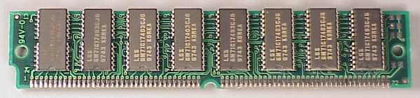
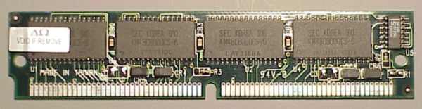
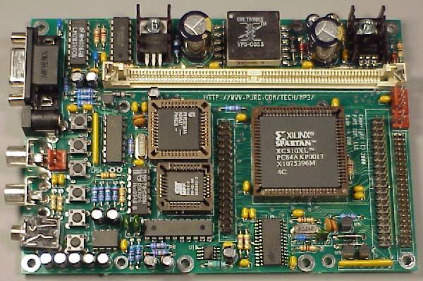
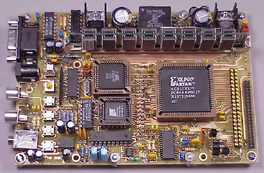
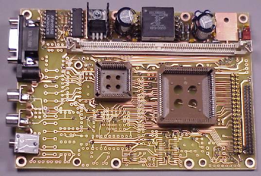
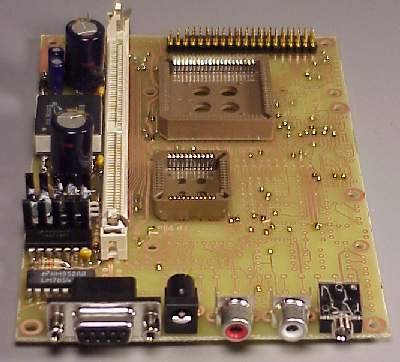
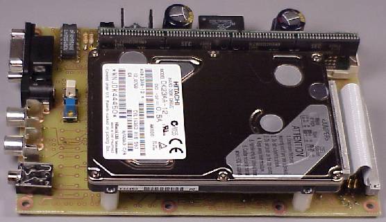
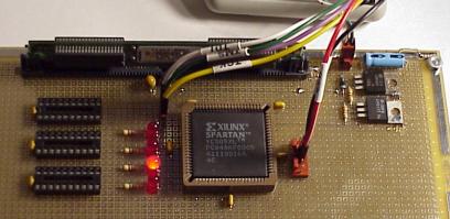 Prototype board, minimal wiring is in place to
be able to configure the Xilinx chip. The SIMM and 20-pin buffer chips
are unconnected (except for power).
Prototype board, minimal wiring is in place to
be able to configure the Xilinx chip. The SIMM and 20-pin buffer chips
are unconnected (except for power).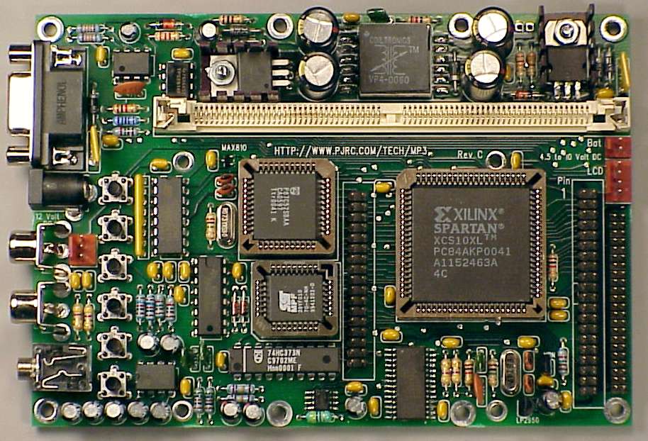
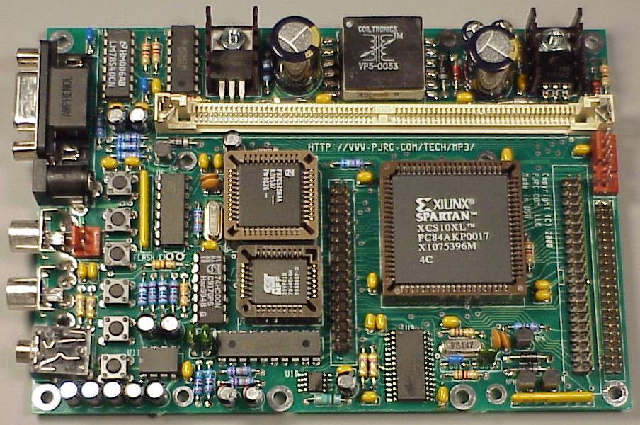
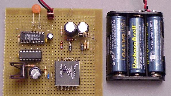