Date: Sun, 02 Jan 2011 23:13:44 -0500
From: Anthony Griggs <ajgriggs AT comcast DOT net>
To: paul@pjrc.com
Subject: Teensy++ project

Hello Paul,

Attached is a project to make a Serial Line analyzer with the Teensy++
board. I needed one and it seemed easy enough to do. Do with it what you
will.

Regards,

Tony Griggs
Salem, CT
File: SerialAnalyzer.zip
(Yet another)
Serial Data Analyzer
by ...
A. J. Griggs
Version 0.1 January 2, 2011
- Overview
The hardware and software contained in the project implements an RS-232 serial data analyzer.
- Hardware
- Based on AVR AT90USB microprocessor
- USB interface to PC
- Cost effective 6 channel RS-232 -> logic levels converter
- Software
- Firmware
- Based on LUFA project for USB support
- Event driven data interface as opposed to constant sample time
- Timer clock is 250khz (16 Mhz / 64)
- PC Software
- Written in Python
- Uses PyUSB module
- Serial module used for implementing test drivers
- Test environment
- Fedora 13 x64 (AMD)
- Avr Gcc tool chain
- 2 serial ports for 'chatter' tests
- Features
- Captures at data rates up to 19200 baud with Python client
- Data rates up to 38400 baud with C client
- SpeedTest module in LUFA kit adapted for test
- Data rates of 9600 bauds with both RX and TX channels 'chattering' with different continuous streams
- Sample Controls
- Start
Starts acquiring sample data for all channels
- Stop
Stops acquiring sample data
- Serial Stream Decoder
Since only the pin change events are captured, it should be possible to implement any 'soft' UART. The asynchronous ASCII UART is implemented as an example.
- Baud rate settings
300,1200,2400,4800,9600,19200
- Parity
- None, Even, Odd *** only None implemented
- Data bits
5,6,7,8
- Stop Bits
1,2
- Output each decoded stream to a separate file
- Decode_0.txt -> Decode_5.txt
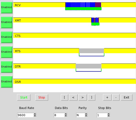
- Trigger markers show sample times for each channel
- Yellow – Idle
- Red – Start bit
- Blue – Data bit
- Orange – Stop Bit
- Grey – Stop bit not found as expected
- Channel Controls
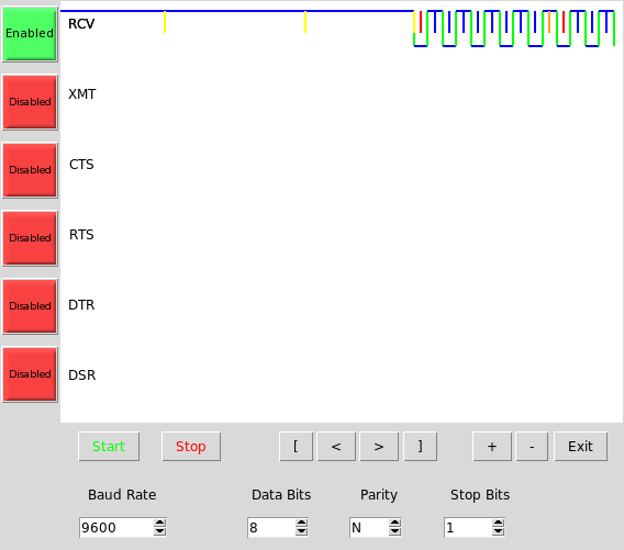
- Enable / Disable channel decoding
Note – Capture runs on all 6 channels always. It would be nice to disable channels in the AVR as well as an enhancment.
- View Controls
The view region is a 512 x 384 pixel canvas.
- Scroll to start (left) end '['
- Scroll to end (right) end ']'
- Scroll right 1 screen at current zoom level '>'
- Scroll left 1 screen at current zoom level '<'
- Zoom
- In to maximum of 1 clock / pixel '+'
- Out to show entire capture session '-'
- Files of Interest
- seranl.py
Seranl.py is the capture control and display program on the PC. Files in the sanl subdirectory relate to this program.
- Exercise.py and ExercisePort3.py
Two serial exercise programs for port 0 and port 3.
- Note: You must run as root for these programs to work unless you have modified the permissions on the serial devices they use.
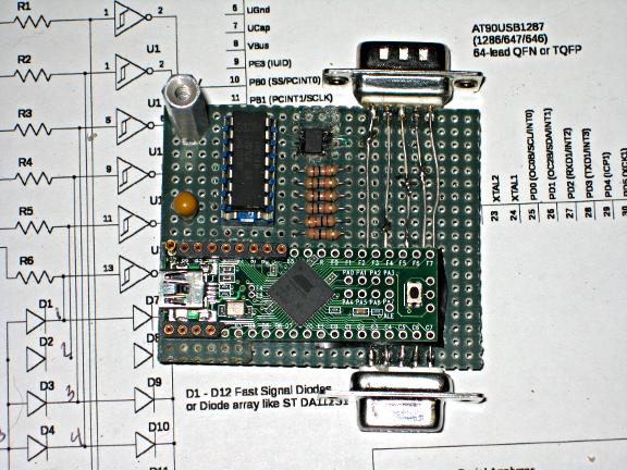
- Firmware
The firmware is based on the Dave Cameron's LUFA package. The LoopBack demo was modified and renamed to Seranl. It is built for the AT90USB1287 chip but runs with the AT90USB1286 chip on the Teensy++ board. I imagine any similar board would work as there is not much on the Teensy except the chip.
- Circbuf.c and Circbuf.h
Implement the circular buffer. The USB interface is running in bulk transfer mode, so while it is moving data, you need a place to save events.
- Seranl.c and Seranl.h
- The modified LoopBack files which
- Setup an 8 bit timer with 16 mhz/64 clock
- Enable the roll over interrupt on the time
- Enable the Pin change interrupts on Port B pins 0 – 5
- Transfer data to the USB when a 512 byte capture is completed
- A byte is also sent to the AVR UART port as an on-board test generator
- Test Software
- Modified SpeedTest LUFA Demo Project
Only the PC based project was modified. Do a make Linux to get an updated copy of the test client. It receives blocks of data from the AVR and only checks for overruns.
- Exercise.py and ExcercisePort3.py
The python serial drivers. You must run as Administrator to if the serial devices do not have permissions for your login.
- Building and Running
The only environment this software has been tested in is an AMD x64 PC running Fedora 13. The latest Python 2.x was used with the Serial and USB module extensions. The AVR gcc tool chain was used for building the firmware.
- Build the firmware
- run the 'make' command in the SerialAnalyzer/Firmware/Seranl folder.
- Build the PRJC Teensy loader CLI for your platform
- Other loaders are available an should also work
- I could not use the GUI loader as it was not built for x64 Linux
The CLI tool works fine for me.
- Load the firmware into the AVR chip
- Set your USB to allow you to connect to the PRODUCTID and VENDORID for the LUFA based firmware. I created /etc/udev/rules.d/49-teensy.rules with the lines
SUBSYSTEMS=="usb", ATTRS{idVendor}=="03eb", ATTRS{idProduct}=="204f", MODE:="0666"
KERNEL=="ttyACM*", ATTRS{idVendor}=="03eb", ATTRS{idProduct}=="204f", SYMLINK+="ttyUSB00%n", MODE:="0666", ENV{ID_MM_DEVICE_IGNORE}="1"
If you don't have the LUFA id's setup, you cannot attach to the AVR usb unless you are root.
After you have done this, reboot or stop and restart the usb services.
- Plug in the AVR to the USB port on the PC
- Run seranl.py in the python/sanl subdirectory:
python seranl.py
You should see the GUI. Push Start and as soon as the button pops out push stop. You should not see any error messages about not being able to find the USB device. When the graph refreshes on the top channel (RX) you should see a band of yellow. Zooming in will show yellow tick marks. These are the event markers for each roll-over of the timer in the AVR. Seranl.py is scanning for its first start bit with the Decoder.
- If you get this far, you have come a long way. If you don't, then build the SpeedTest project for the PC in the LUFA Demo area (make Linux) and run it. You can enable printouts in the project to see if the events are coming from the AVR. There should be a steady stream of them as the 8 bit counter will roll over every 256/250000 seconds.
- If things seem to be working, hook up a serial port to the device, or tie the AVR's uart out pin (PD3) to PB0. Push start and after a second push stop. You should now see some data captured on the top (RX) channel. Zoom and scroll until you can see the bit pattern. It should look something like below. You must have matched the settings of the transmit UART to decode the stream. 'U' s are stress test characters as they have a transition every bit.
- Yellow – waiting for start bit in idle state
- Red – center sample of start bit. The remaining bits will be spaced at multiples of one bit time from the start bit.
- Blue – sampling time for data bits. UARTS output data from LSB to MSB.
- Orange - stop bit found
- If you have the wrong UART settings, you don't have to recapture the stream. Just change the settings in the dialog below the graphic canvas and cause an update by scrolling or zooming.
- Theory of Operation
- Firmware
- Capture Stream Data Format
A capture event consists of two bytes
- Data and status byte
Bits 0-5 are the Port B pin states
Bit 6 is the Overrun status bit
Bit 7 is the roll over status bit
- Timer value byte
- AVR processing
- Timer0 is set to free run at a 250khz rate. Every 256 clocks when it rolls to zero, an interrupt is generated. This will insert a rollover event into the capture stream.
- A pin change interrupt on PORT B pins 0-5 will also trigger an interrupt.
- Both roll over and pin change interrupts constitute an event. Each event is stored in the circular buffer.
- If the buffer returns 'Full' status, a global Overrun flag is set. The flag is applied by the foreground loop the next time an event is retrieved from the circular buffer to build the staging buffer for USB transfer.
- When the staging buffer is full (512 bytes) the USB transfer routine is called.
- The USB transfer takes multiple passes at 64 bytes / pass to transfer the entire staging buffer.
- When the entire buffer is transferred, the foreground loop again starts filling the staging buffer from the circular buffer.
- Python (Seranl.py)
- Capture thread
A separate thread is spawned to capture the event transfers from the AVR when the Start button is depressed. The connection to the AVR is made at this time. Capture continues of the two byte pairs until the Stop button is pressed. At this point , the raw capture data has 8 bit timer values that continually roll over. The raw data is filtered into a second list that creates a common time from the first event captured. That is, the first event is at zero time.
- Display
At the conclusion of the Capture process, the GUI requests the entire filtered list from Capture to Draw the Slice. DrawSlice iterates over all the active channels to draw the from the received slice from Capture.
- The limits of the slice are modified by the scroll and zoom buttons and the entire display is redrawn.
- Decoding
Decoding is called at the end of the drawing phase based on the extents of the filtered capture buffer. A software UART is implemented which is applied to each Enabled channel in succession. The UART must be in the IDLE state before finding the first start bit for reliable decoding. Once the start edge is found, ½ the bit time is added to the edge and this becomes the basis for sampling all the remaining bits. One bit time, as computed from the selected baud rate and known timer clock, is added for each bit ot be decoded. Each decoded byte is printed to the console that launched seranl.py and writted to a file Decode_<chn>.txt where <chn> is the current channel number 0-5.
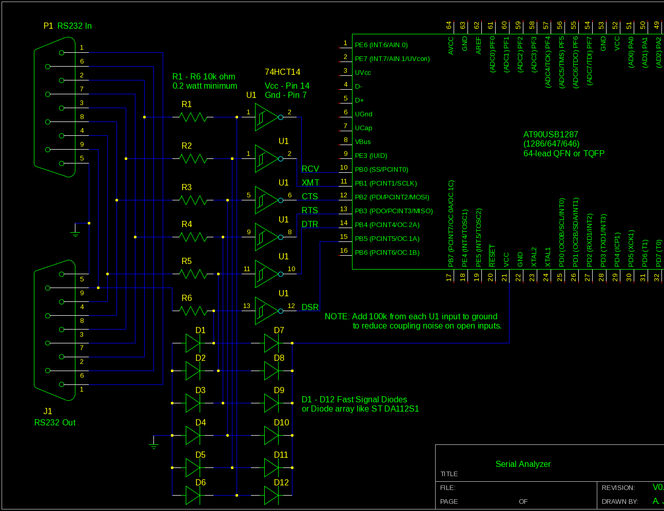
- Hardware Front End
RS-232 levels must be converted to AVR logic levels. Normally, a chip like the MAX232 would be used, but they only have 2 receivers and also carry 2 transmitters which are not needed. 3 MAX232 chips would be required for the six inputs monitored. And, each MAX232 has several charge pump capacitors as well.
The MAX232 is the straight forward way to go. But since we are only monitoring inputs and not transmitting anything, simply clamping the RS232 levels to 0 and VCC is sufficient. A resistor input followed by a diode array to clamp the signal and a common 74HC14 schmidt trigger are used to process all 6 channels. It is not exactly to RS232 specs but should function well for most RS232 signals.
- Note: a 100k ohm pull down to ground has been added to each 74HC14 input to eliminate the coupling on open lines.
- Enhancements
The following items would be nice to have.
- Faster capture speed in python
- Decode from the start of the capture, but display only based on Zoom and scroll.
The current decoding is from the current view, and if that is not on a word boundary, incorrect decoding results.
- Pluggable decoders for other types of data
Including plugging in the GUI elements that go with them.