|
|
| ||
|
Shopping Cart
|
| Home | Products | Teensy | Blog | Forum |
|
You are here:
MP3 Player
|
|
|
User Photos:Here is one photo, with a link to the other photos (which have captions). Can you please add it to the user gallery? Thanks! BTW, I'm enjoying constructing the enclosure, and I can't find a good car audio amplifier for the midrange/highrange speakers, so wish me luck. Sometimes it would be easier to live in the USA (shipping and duty etc are slaughter-rific). http://www.geocities.com/brubblecaptain/mp3/photos.htm
Okay, here are some early photos of the project, with explanations.
I apologize in advance for the poor quality, possible typos, etc. Also,
the photos are not in chronological order, but progressive order (I mean,
I didn't do things in the most logical order, but if I redid it, this is
how it would go).
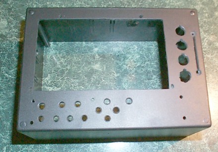
First, the empty enclosure.
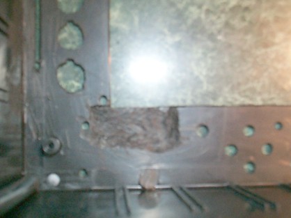
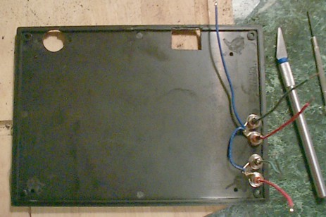
From the back, you can see how I had to grind out a bit of the case to make room for the display connector (which is taller than most of the other components on the keypad.
Now, with the keypad and screen installed, you can see where the connector fits in that pit I had to grind out.
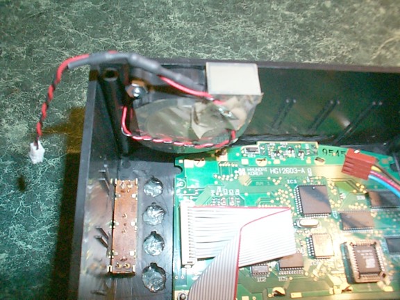
I noticed that the heatsink was warm while the player was running, so I figured I wanted the option of a cooling fan. I added a second, taller heatsink to the main power supply transistor, which sits just in front of the fan; the player PC board sits flat on the back cover of the enclosure, with some space between it and the display/keypad. The fan exhausts out the back of the player. Here is a photo of the fan in place. It's covered with tape to prevent ABS plastic dust from getting in and ruining it when I'm dremeling. The rectangular brown taped part is the exhaust hole, which is flush with a similarly sized hole I have cut in the rear cover of the enclosure. Eventually, I may add a cool air intake near the front or side of the player so it can enjoy fresh, cool air. But then again, it may not even be necessary to cool the unit. It doesn't get really hot yet. I may also add a thermistor-based control circuit for the fan so it only activates when necessary.
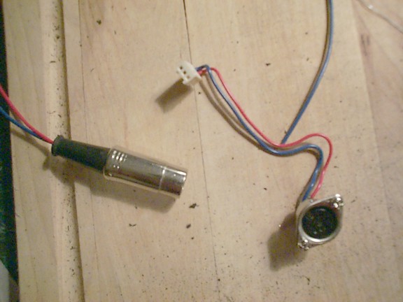
Here is the power connector. I bought a DIN pair from a local surplus shop (Add Electronics). It's a seven-pin or so... I wanted extra pins for future expansion. =) The socket mounts to the rear cover of the enclosure, and then connects to the board with a molex plug (bought locally at Active).
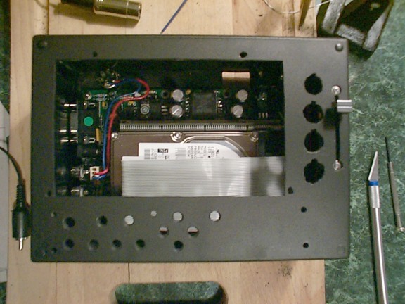
I installed two pairs of RCA output jacks. One pair is for normal output, for a full-range amplifier/speaker setup. The other pair is for subs; it will be wired in parallel through a stereo 50K slide pot, so the bass can be turned down in quiet neighbourhoods or when stopping at traffic lights. You can also see the round hole on the top-left for the power socket, and the rectangular hole that mates with the fan exhaust vent.
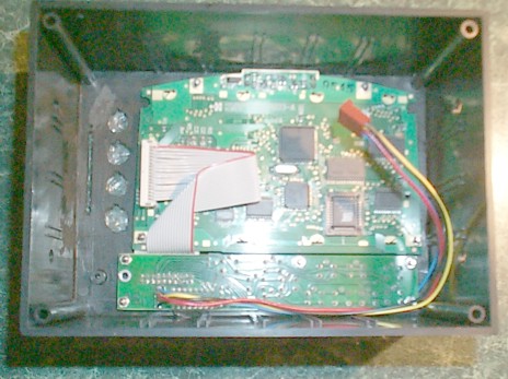
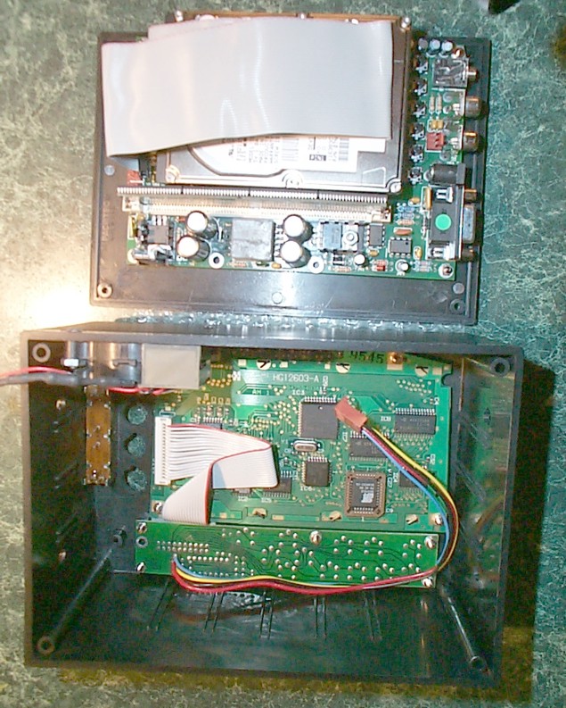
Okay, this large picture shows the main circuit boards mounted on the enclosure. The enclosure is oriented like a wide-open clamshell; that is, in order to close it, you have to fold the rear panel (on which the player board is mounted) up onto the box part, and then screw it together. On the bottom-left of the player board, you can see the power supply transistor with the extra heatsink. You can also visualize how it will sit just in front of the fan's intake. Sweet. Adding new files to this setup will be a major PITA, but I intend to rip 'n' encode my entire CD collection only once, and be done with it. And perhaps whenever I buy a new CD, I can go to the bother of opening it and copying new data. But more likely, as soon as this puppy is done, I'll start on a version 2 enclosure... with a removable hard drive mechanism. =) (In this photo, I hadn't yet cut the holes in the rear enclosure cover).
Here, you can see the player board mounted on the rear cover, and the rear cover installed.
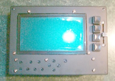
Finally, the fully-assembled player, seen from the front. The protective plastic is still on the LCD, and the picture has been gamma-adjusted because it was too dim. Note the four large buttons on the right, next to the "politeness control" (the bass dimmer slide pot). These line up with two rows each of the LCD. The idea is to have soft-buttons in future. A fifth button will be added on the lower-right for enter/cancel/next-menu/something. Also, note how bad the chrome screws look. I'm probably going to countersink them, and then paint them black, or find/buy black equivalent screws. I'm also likely to paint the chrome slider knob matte black. Naturally, I'm going to want to add EL lighting or some way of having the display work in the dark. Hmm... a flashlight in the center console just seems... tacky? =)
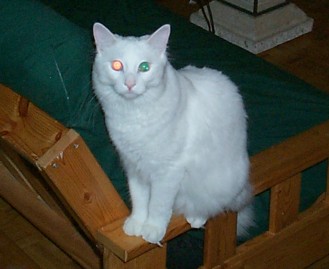
Here is my lab assistant, Prism. The photo is cropped, but otherwise unchanged. His eyes, naturally one blue and one green, look like LEDs, don't they? But I assure you, he's 100% biological. Just check the catbox for proof. =) My girlfriend declined to appear here, but she's playing Jak and Daxter in the background on the futon on which Prism is perching. Details and ramblings:
What's Left
|