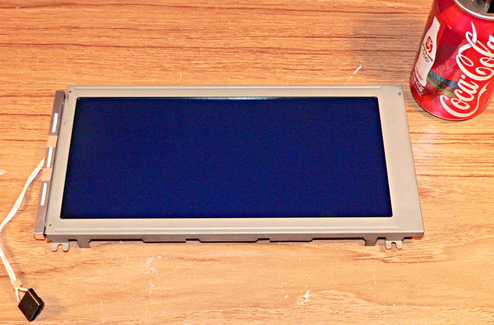
Last nice Ben brought a Micros 2700 POS terminal to the meeting. Here is one of the LCD screens:
The LCD is a Emerging model EG64E00BCWU (nice of them to put a sticker on the back side with the model number). Here is a datasheet for the LCD:
http://www.pjrc.com/tech/eg64e00bcwu/eg64e00bcwu.pdf
Yes, it's 640 by 200 pixels with a CCFL backlight!
Unfortunately, the LCD doesn't have the controller chip (with nice interface) with a frame buffer built on board. It's on this similarly large card.
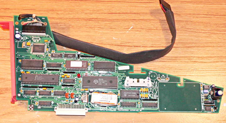
The QFP chip in the upper right (U1) is the controller chip. It's made by OKI and has "M6255" printed on it, which at first seems to turn up only datasheets for opamps. It turns out the part number is actually "MSM6255", and here is the datasheet:
http://www.pjrc.com/tech/eg64e00bcwu/msm6255.pdf
The frame buffer memory isn't built in to the chip. That 28 pin part right below it seems to be the frame buffer memory. The MSM6255 has 2 busses (both 8 bit data, 16 bit address), one which connects to the frame buffer memory chip and the other to the CPU's memory.
That big chip in the center is a Z80 processor, and the two memory chip above it appear to be the firmware and RAM it uses. The big chip right below the frame buffer memory is a IDT7132 dual-port RAM chip, which I believe the designers used to communicate between this Z80 and the main Z80 that runs the rest of the terminal (together with several other Z80s). But really, who cares about that? I just want to figure out how to scrape all that stuff off and get access to the display....
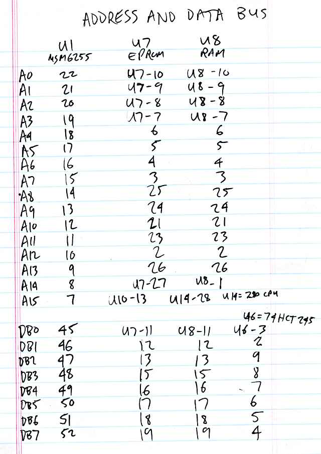
So, with a printout of the MSM6255 pinout, I started tracing out where signals connect. The Address and Data busses are pretty straigtforward. I didn't trace the to the Z80 and dual-port RAM, though I'm pretty sure they go there. My intention is to pull all those chips off and drive the bus with my own micro.
Tracing the control signals is harder. They are connected to pullup resistors, so all over the place my meter auto-ranges from megaohms down to kiloohms, which makes the process so slowly. Anyway, here's what I've learned so far.
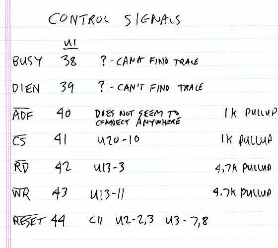
It also seems not all the power pins of all the chips are connected together. The LCD and its frame buffer, for example, do not connect to the same power as the Z80 and its memory.
More to come....
My hope is to get this thing working with a AVR, so everyone (who gets one from Ben) can play with one of these huge screens.