Teensy to XBee Adaptor Kit
| Discontinued | KIT_XBEE_ADAPTOR | XBee Adaptor, Unassembled Kit | $6.00 |
|
This kit lets you easily connect Teensy to a XBee wireless module.
This kit is not recommended for new designs. It will be discontinued after remaining stock is sold. For a long-term XBee solution, please use this Sparkfun product.
The Arduino XBee Library is fully compatible.
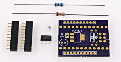
Kit Contents:
|
Items Not Included:
|
Assembly Steps:
1: Trim board edges.
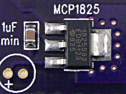
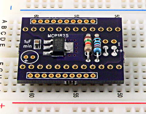
2: Solder MCP1825 and 1 µF Capacitor
Tweezers should be used to hold the each part in place while soldering the first pin. The MCP1825 tab should be soldered last. The iron may need to be left in contact for many seconds to transfer enough heat for the solder to flow.
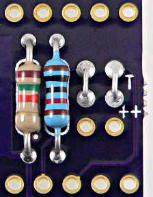
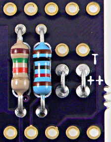
3: Solder 10K & 15K Resistors
The 15K resistor has a tan body, with stripes: Brown, Green, Orange, Gold.
The 10K resistor has a blue body, with stripes: Brown, Black, Black, Red, Brown.
4: Solder 2 jumpers to configure for Teensy vs Teensy++
| Configured for Teensy | Configured for Teensy++ | |
|---|---|---|
 |  |
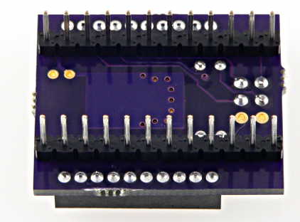
5: Solder Headers or Sockets for Teensy
You will need headers and/or sockets soldered between the XBee adaptor and Teensy. When soldering headers, a breadboard can be used to hold them straight.
6: Solder sockets to XBee
Teensy LC, 3.0 & 3.1 & 3.2 Usage
This XBee adaptor was original designed for Teensy 2.0 and Teensy++ 2.0. However, it can be used with Teensy LC & 3.x with the following changes:Configure the adaptor for Teensy 2.0. That will route the signals to pins 7 and 8, which are Serial3.
You'll need XBee 0.4. This newest version lets you configure which serial port it uses. In your code, you'll need "Serial3.begin(9600)", and then "xbee.setSerial(Serial3)" to use that port.
Do not use the 15K resistor. Or if you've already soldered it, just cut it off the board. Those 2 resistors divide the 5V transmit signal from Teensy 2.0 to only 3 volts for the Xbee. On Teensy LC, 3.0 and 3.1 and 3.2, the signal is already 3 volts. It's fine to leave the 10K resistor in place. You could also just solder a wire instead of the 10K resistor. Either way is fine.
If using the USBtoSerial program to test, you'll need to edit the code to use Serial3.