|
|
| ||
|
Shopping Cart
|
| Home | MP3 Player | 8051 Tools | All Projects | PJRC Store | Site Map |
Parallel Port or Serial Port solutions have existed, but many modern computers no longer have these ports. The FTDI USB-to-serail chip can be used as well. Until now it's been widely thought impossible to solve the Chicken or Egg problem using only USB, without preprogrammed or specialized USB chips.
HUB ISP can write an AVR chip using only a USB hub, one cheap/common logic chip, and a few resistors.
 |
| More images below... |
Theory of OperationUSB defines a device reset state, where a hub shorts both data lines to ground for 10 milliseconds. USB hubs also implement a disable feature, where no data is routed to the disabled port, and both data lines are kept at high impedance. Devices contain a pullup resistor, which is used by the hub to detect device arrival, at a disabled port.Normally these features are managed automatically by your operating system. But by taking control of a hub and keeping its ports disabled, each port can be used as a single bit input, and/or a momentary active-low "open collector" pulsable output. Two pulsable outputs can drive a set-reset latch to create a single steady-state output. These I/O capabilities are sufficient for AVR ISP programming! |
Ready-to-use boards like Teensy (yes, a shameless plug, as I make this one) or Arduino just plug into any USB port and are ready to go, with easy to use software tools. Troubleshooting electronics and software can be taxing even for experienced engineers, so it's highly recommended to start with a foundation that's as trouble-free as possible. HUB ISP is, well... not.
HUB ISP is certainly not a viable replacement for regular "chicken or egg" AVR ISP programmers, which are much faster and more reliable, and maybe even cheaper... eg, Teensy running the ArduinoISP code (yup, another shameless plug).
However, if you love to tinker or you're just curious how this could possibly work with only USB and no programmable chip, without even any parts designed for USB, only logic gates and resistors, then read on!
| Qty | Item |
|---|---|
| 1 | USB Hub + Cable (if not part of the hub) |
| 4 | Expendable USB Cables |
| 1 | 74HCT00 or 74HC00 chip (HCT=best, HC=ok) |
| 4 | Resistors, 4.7K |
| 2 | Resistors, 330 ohm (220 to 470 would work just fine) |
| 2 | LEDs - for testing |
| 2 | Capacitors, 0.1uF |
| 1 | Crystal + 2 capacitors (only needed for reprogramming chips) |
| 1 | Pushbutton (or you can momentarily touch reset pin to +5 volts) |
| 1 | Breadboard + Wires, or some way to connect stuff |
| 1 | Cardboard and double-stick tape |
| 1 | PC running Linux, with a USB port of course! |
Update: charliex has attempted a HUB ISP port to Microsoft Windows. It's untested so far.
Before compiling, plug in your hub and type "lsusb" to find its vendor and product ID numbers.
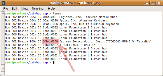 |
You must edit config.h and include those ID numbers. Then just compile with "make". If you get an error about "usb.h" missing, you probably need to install a "devel" libusb library package.
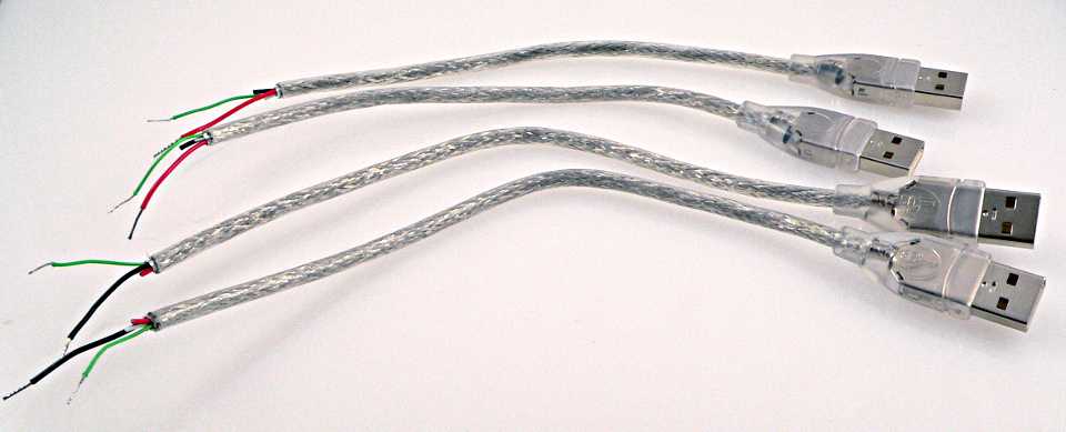 |
It's a good idea to cut the extra white, red and black lines at slightly different lengths, and not close to the frayed metal shield, so they don't accidentally short to each other.
If you have a soldering iron, tinning the ends of the wires will make them much nicer for sticking into the breadboard holes. Otherwise, just twist them tightly and watch for stray bits of wire later on.
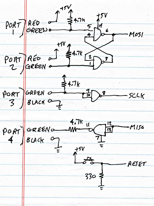 |
| Opps, I drew ports 1 and 2 with red wires and ports 3 and 4 with black wires on this schematic, but I actually used the cables with black wires on ports 1 and 2, and the cables with red wires on ports 3 and 4. It doesn't really matter, as all 4 red wires connect to the same +5 volt power inside the hub and all grounds are connected together. Even just 1 red wire and 1 black wire from any of the 4 cables is enough. Of course, it DOES matter that each green wire goes to the correct place. The test program will help you make sure it's all hooked up properly before risking a real AVR chip. |
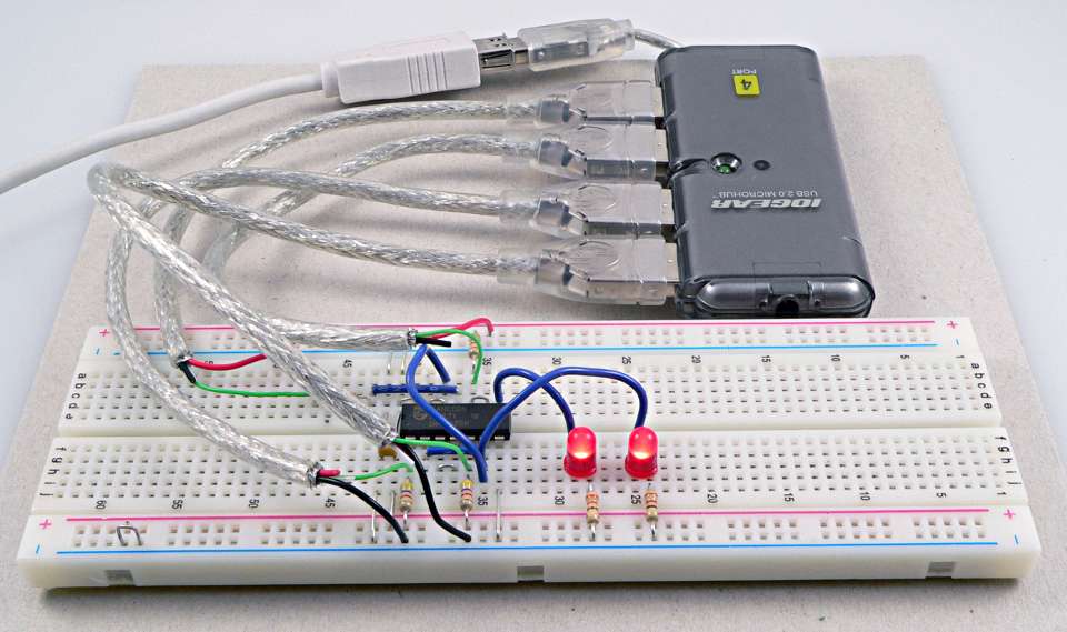
Here is a closeup photo of the circuitry. There is a 4.7K resistor, the one attached between pin 11 and port 4's green wire, hiding behind one of the USB cables!
This picture also has 2 LEDs connected to MOSI and SCLK, and a wire connecting MOSI to MISO. These are temporary, only needed for the test program.
 |
This diagram of the 74HC00 chip can be helpful if you're following the schematic.
 |
Be sure to add a 0.1 uF decoupling capacitor close to the 74HC00's power pins, and later when you add the AVR chip, put another one right on its pins 7 and 8. You're getting power through several inches of USB cable, probably the cheapest possible cables since you were willing to chop them up, and that power is coming from a hub which is probably also cheaply made, so please don't skip the decoupling capacitors. Use good quality ceramic (eg, X7R type) capacitors placed close to the power pins!
Taking a moment to secure the breadboard and hub to a piece of cardboard (or anything sturdy) with double sticky tape will save a lot of frustration. Those USB cables are rigid and the slightest motions seems to yank the tiny green wires loose.
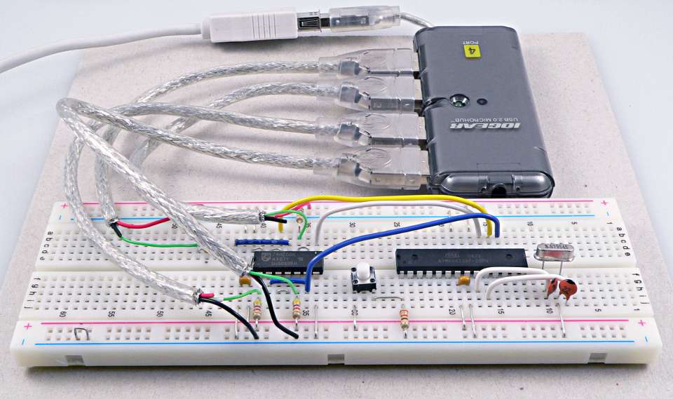
When it's all wired up and looks like this, you're ready to run the test program.
 |
Just run "hub_test". If everything is connected properly, you should get all tests to pass, and you'll see the LEDs blink as described. If any test fails, now is the time to get the wiring working properly, before you connect that AVR chip!
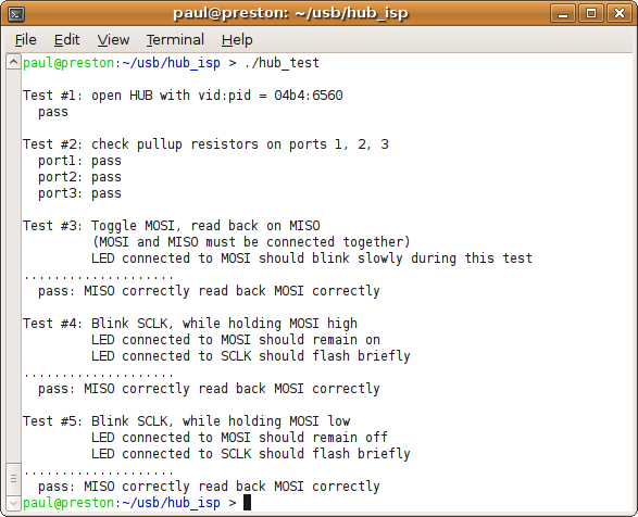 |
When you first plug in the hub, Linux will think 3 or 4 new USB devices have been attached, due to the 4.7K resistors, and it will create a bunch of activity on the hub. The first time you run "hub_isp", it will be out of sync and should ask you to reset the chip and try again. Just press the button, and the second time things should work.
 |
| High Resolution Image Available |
When a chip is a brand new virgin, it will use its own internal oscillator. However, if it's ever been programmed to use a crystal, it will require a crystal connected to pins 9 and 10. The value doesn't matter. I used a 3.57 MHz crystal and two 22 pF capacitors.
When you run the "hub_isp" program, it will write the arduino bootloader into the chip. The screen should look like this:
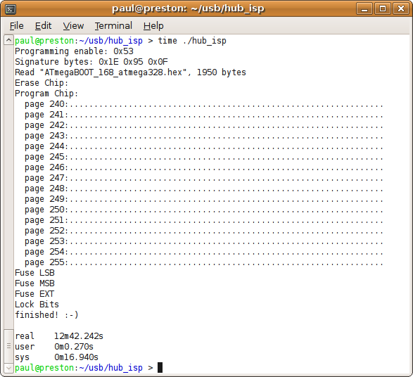 |
It takes almost 13 minutes to write all 1950 bytes, because the USB reset pulses are 10 milliseconds long, and AVR ISP protocol. requires at least 32 for every byte.
But speed aside, you can indeed write the arduino bootloader (or anything) into a completely blank ATMEGA328 chip without any pre-programmed parts, using only USB, with only a hub, a simple logic chip and a few resistors and other cheap, commonly available materials!
I was able to write the chip successfully many times with no other programs running, but when I used Firefox on several graphically rich sites with lots of javascript, programming would fail. I even bricked one chip! It may be recoverable with the parallel programming technique, but that's a whole new "chicken or egg" problem....... hmmmm............
Beware if you try this, do so with as little else running as possible.
Perhaps someone experienced with Linux's real time scheduling API could improve this code? With very reliable millisecond-level scheduling, it might be possible to avoid the NAND gates, and simply pulse SCLK while MOSI is known to be be within a pulse (for low) or not within a pulse (for high)? With kernel level programming, it should be possible to use the root hub inside the USB host controller on the motherboard's chipset, instead of commandeering an external hub.
Maybe an AVR could be programmed with nothing more than 3 USB cables and 3 resistors?!
But please do not ask for tech support, and especially do not ask me for a windows version! The code is GPL'd, so edit any way you want...